Beware of cheap underperforming clones

As of 2022 there are many badly performing clones on the market. V2/3GHz NanoVNA uses parts like ADF4350 and AD8342 which are costly and clones have been cutting costs by using salvaged or reject parts.

See official store and look for V2 Plus4/V2 Plus4 Pro versions only to avoid getting a bad clone. We have stopped selling V2.2 versions since October 2020, so all V2 hardware that are not Plus or Plus4 are not made by us and we can not guarantee performance.

NanoVNA V2 Forum

Note: this page is a mirror of https://groups.io/g/NanoVNAV2.
Click here to join and see most recent posts.

Mechanical Dimensions #documentation


Chuck 2020/06/27 12:37

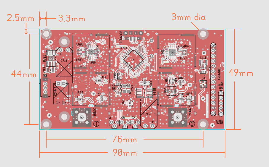
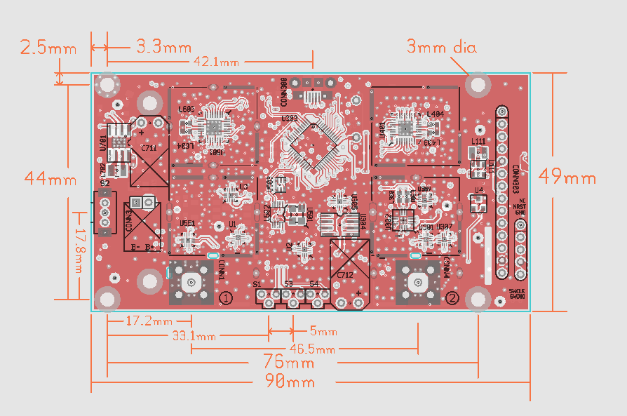
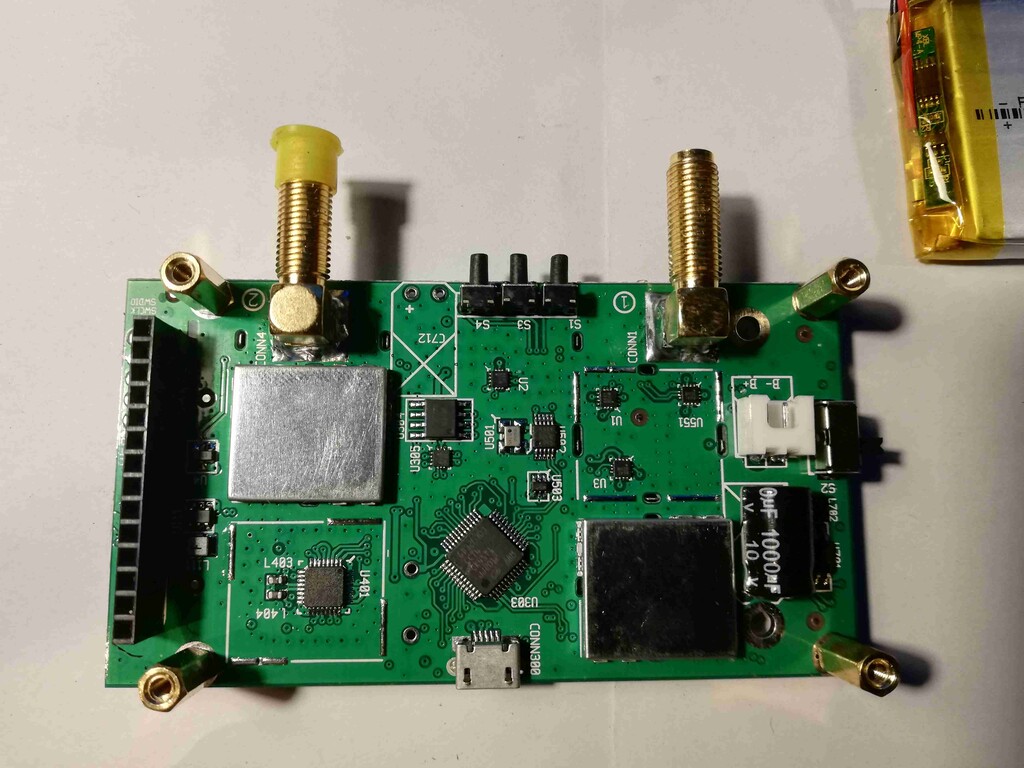
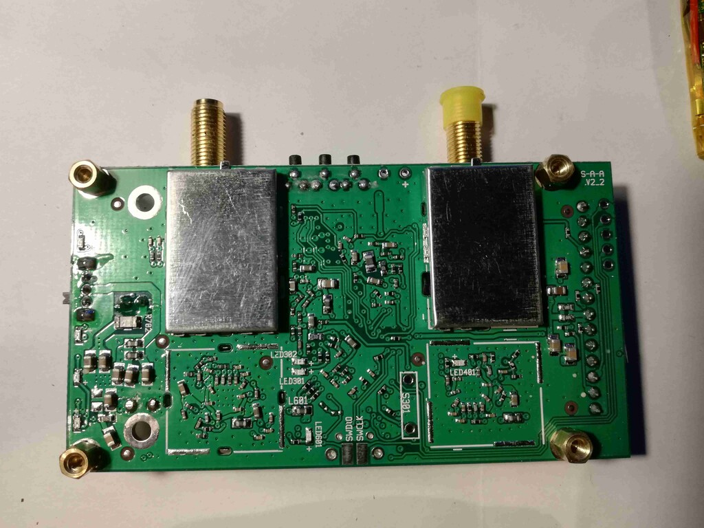
I have tried the two print designs for cases that have been shared here, neither felt as a durable or as robust as I would like. I would buy the metal case if it were available, and I don't mind paying $20 for the printed case on Tindie but I cannot fathom paying another $20 to send it to the US (bringing the total cost to nearly as much as the unit itself), so I started designing my own case. Unfortunately, I haven't found an official source of the mechanical dimensions for the unit, if there is one PLEASE let me know. In the mean time I dug out my caliper and with the use of my 3D printer to make "check plates" I have put together a set of mechanical dimensions that work for the unit I bought from Tindie. I've attached them as a PDF (its one of the formats my CAD program, TurbCAD, will produce).

Some notes on this dimensions:
* All of the dimensions are in mm which makes them more compatible with most 3D printing packages
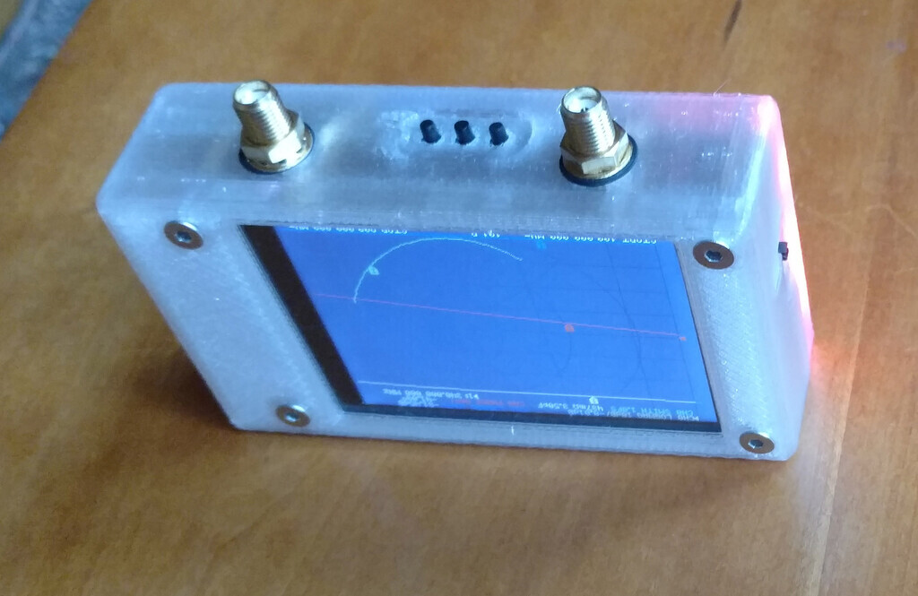
* The outline of the 'face' represents edge to edge of the PCB with no overhang, so if you're making a case you'll want to extend the edges on sides to get overlap
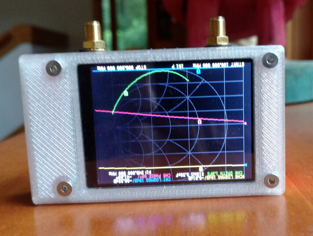
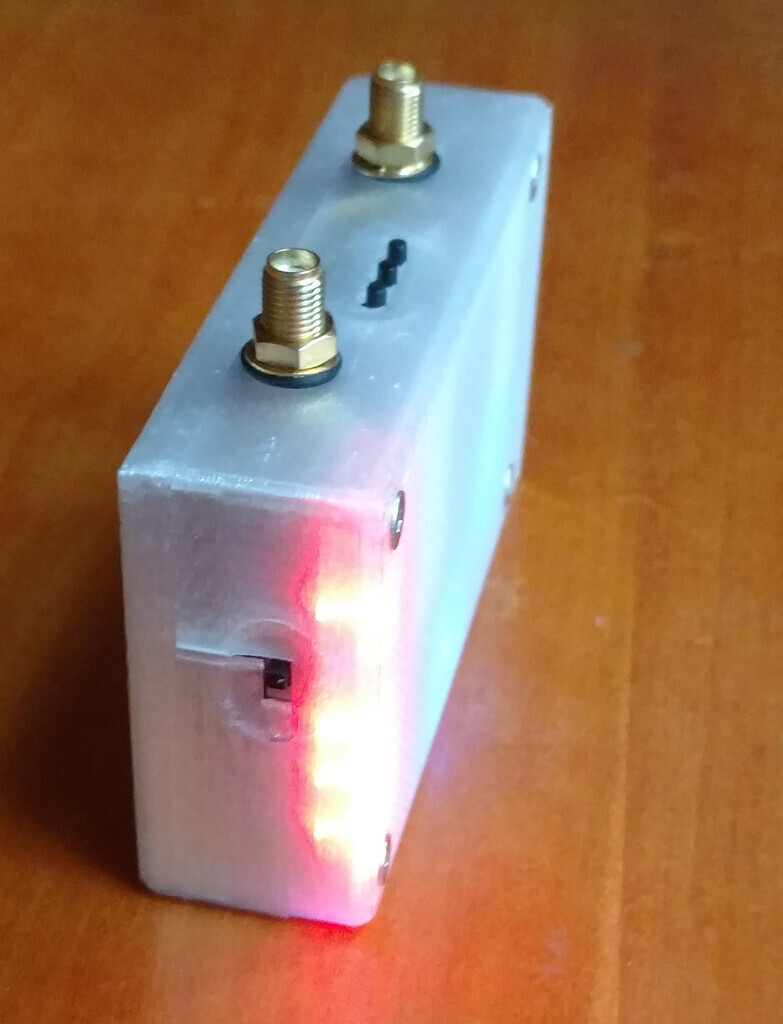
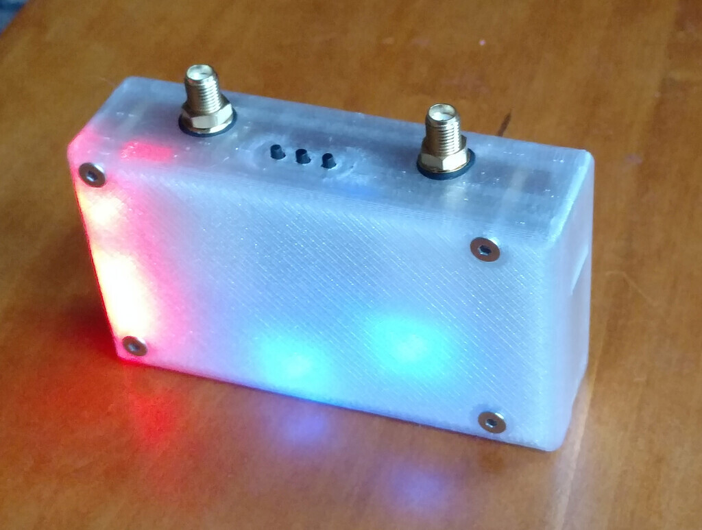
* I printed out my tests as 2 mm "thick" sides, so the recesses (one for the power switch, one for the USB port) are 1 mm "deep".
* I deliberately chose not to use the **actual** outline for micro-USB on the USB port
* Neither the "bottom" face, nor the "left side" face are included as neither have openings. they are simply a 90.5 x 50mm square and a 50 x 22mm square respectively.

I don't warrant these will work on your unit. Clearly manufacturing differences can have an effect as can part substitution, that said, they should be on the paper at a 1:1 scale so if you print out this sheet and measure the printout to see that the dimensions your printer prints are accurate, then you can use an exacto (small razor) knife to cut the openings out of the paper and "test fit" them on your unit to verify.

Hope someone finds this helpful,
--Chuck

Tony Abbey 2020/06/27 12:53

Hi Chuck

Have you got an STL file for the 3D print?

Tony

Chuck 2020/06/27 13:09

True to form, once I posted this I saw a couple of bugs (missing dimensions, no version number), so I've updated it.
And a slightly less heavy line on the pieces.
--Chuck

Chuck 2020/06/27 13:12

Yes, but they are just the 'faces' if you will. They are attached, as I was iterating as I did this (print test fit, adjust my drawing, repeat) they have individual "version" numbers.

--Chuck

Tony Abbey 2020/06/27 13:34

Thanks Chuck - I can assemble these together in Repetier Host. I also see there are files on Thingiverse - not sure yet if they are for the V2.

Tony

Chuck 2020/06/27 13:59

Hi Tony,

Be aware that if you do that the case will be "too small" since they don't include any overlap. If you print them out and hold them against your NanoVNA you will see that the join at the very edges but do not over lap. You will need to add material to them in order to make that work. Or you can wait for the case to be done. There are two cases on Thingaverse (I've printed them both) and they both work although they have different issues with them. (mostly in fit and finish, and how they are held together), I've corresponded with the author of one of them about ways to improve their fit and finish but they are not a mechanical engineer and it isn't easy to communicate visual things in text.

Since the individual faces take like 25 minutes to print on a Prusa MK3S consider just printing the STL files and see for yourself what I'm talking about.

--Chuck

Neon22 2020/06/27 16:34

I'm working on a case at the moment. I use openSCAD a lot.
Attached is my internal volume representing the NanoVNA v2. My measurements are not as precise as @chuck and I will update.
I use this with the difference operator to subtract it from my external solid case blocks.
I'll be posting it on Thingiverse when done. I'm going to use an 18650 myself but will also allow for a flatpack lithium pack.

Chuck 2020/06/27 20:49

So for what it is worth, I did a test shell with my dimensions. You can see pictures of it here: https://photos.app.goo.gl/dKDSw4rVih95kRSo6

That is using the attached STL file. It took an hour and 52 minutes to print on my Prusa.

Because the front face has a big opening in it, there is enough compliance (for PLA anyway at 20% infill) to start the side with the SMA connectors and flex it a bit so that you can get the USB side over the front and then down to the other side. I don't have a 'worst case' over molded USB cable to test but the existing relief seemed to be sufficient. As the relief depth is only 1mm it isn't enough overhang to give the printer problems.

The front face has to be printed flat of course since there isn't really any good way to bridge the opening so the orientation in the STL file (front face down, sides vertical) was the orientation I used.

At this point printing the second half of a "clam shell" type case would be pretty doable but the closures to hold the halves together are still an open issue. With a clam shell design you would want lap joints between the halves and so you would probably want to bulge out the overlap area. 2mm walls are reasonably strong (could be made stronger still by increasing infill at a longer time to print) but that makes flexing harder, you could make the SMA holes ovals to allow for clearance while slanted which might not be too bad as the washer/nut would probably cover that.

Still on the fence about whether or not observation holes in the bottom would be useful for the LEDs. I do think access to the SWDIO port could be handy so looking at how hard that would be.

Like the 'stylus holder' idea. Not sure how easy it would be to do that but it would be cool. One side piece is just blank so adding a 'stylus pocket' on that side would be pretty easy.

More work to do.
--Chuck

aleks07111971 2020/06/27 20:53

Case Example

Chuck 2020/06/27 21:18

That is pretty interesting. I like how you re-used the mounting screws for the display to keep the case together. And the battery bulge is interesting too. TBH I'm not particularly interested in running on battery power so had not put a lot of thought into that aspect of it.

aleks07111971 2020/06/27 21:22

Found an example on a Russian site. I will do under the 4-inch display.

MarkZ 2020/06/28 03:44

I made this case from Thingiverse https://www.thingiverse.com/thing:4285813 and quite like it.

Mark

Chuck 2020/06/28 12:46

Yes, that is the second one that I printed from Thingaverse as well. I don't have any M3 bolts on hand so I had to fudge a bit and replace the spacers and bolts with 4-40 equivalents (not recommended as you can't really match the spacers and sizes so the boards are fractionally out of square when you do this).

Things that I like, was the re-use of the existing mount holes. I had not considered a translucent filament to get access to the LEDs, that is pretty neat.

What I was concerned with were the lack of lap joints on the edges, also not a huge fan of the recesses on the menu buttons but that is a personal preference. I reached out to the designer in the comments section and they may make those changes (or not of course)

As your pictures point out, the "natural" way to operate this unit is with the SMA connectors "up", the default is wrong way up on the display :-) but that can be flipped from the menu. I'd like to have something of a "kickstand" that let me put the device on my bench at a good viewing angle since the screen is very sensitive to that (I can't see the smith chart lines if I'm not looking at it nearly perpendicularly)

My Tindie unit came with a SOLT kit, cables, and a stylus (which is really helpful) so I like the idea of a stylus holder as well. In my notebook I've got a couple of ideas that have both a 'storage' are for the stylus as well as an 'available' holder so that its easily accessible.

Lastly, seeing Hugen's metal case, they have added "wing" like structures that protect the SMA connectors a bit. That is a nice touch and lets you set the unit on any edge. It does take up a bit more room but I am not space constrained.

Anyway, to make a case I needed the mechanical dimensions, couldn't find those anywhere, so I did measurements on my unit and did some early 3D printing work to validate the measurements. I'm thinking I can avoid the unsightly "top bolts" by using some brass inserts in the top part of the case, make the board spacers unthreaded, and then you could just bolt from the bottom and pull the case pieces together. With some structures in the case to insure alignment I thing I'd bee pretty happy with that.

--Chuck

Chuck 2020/06/28 13:05

And another test shell with the SMA holes with a 'diagonal' cut through them which makes it easier to slide on and off.
--Chuck

OwO 2020/06/30 00:04

See attached. You will also need the LCD mechanical drawing to know
where the display opening is:
http://www.lcdwiki.com/images/d/d7/MSP2807-002.png

OwO 2020/06/30 00:20

Actually forgot to include the buttons and connectors, here's the
updated diagram

Chuck 2020/06/29 10:24

Wow thanks Gabriel!

If you have the part numbers for the SMA connectors and the buttons then putting together an accurate elevation from this data will be much more precise.
--Chuck

OwO 2020/06/30 02:08

The buttons are:
https://lcsc.com/product-detail/Tactile-Switches_XKB-Enterprise-TC-1109DE-C-J_C571341.html
(the 8mm long variant; some older devices and other manufacturer's
devices use 7mm or shorter ones). The length is measured from the back
of the button to the tip.

SMA connectors are the "SMA-KYWE" variant (see attached).

Siegfried Jackstien 2020/06/29 20:28

fwiw ... thats what I got for 60 eu (postage included!)

i left away the two blue coax cables and the calibration kit

greetz sigi dg9bfc

Am 29.06.2020 um 18:08 schrieb Gabriel Tenma White:

To reply to this topic, join https://groups.io/g/NanoVNAV2