Beware of cheap underperforming clones

As of 2022 there are many badly performing clones on the market. V2/3GHz NanoVNA uses parts like ADF4350 and AD8342 which are costly and clones have been cutting costs by using salvaged or reject parts.

See official store and look for V2 Plus4/V2 Plus4 Pro versions only to avoid getting a bad clone. We have stopped selling V2.2 versions since October 2020, so all V2 hardware that are not Plus or Plus4 are not made by us and we can not guarantee performance.

NanoVNA V2 Forum

Note: this page is a mirror of https://groups.io/g/NanoVNAV2.
Click here to join and see most recent posts.

VNA output level?


Paul Randall G3NJV 2021/10/26 13:24

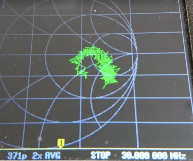
I recently bought a SAA-2N 4" screen in the metal case with N connectors. Used stand alone it seems to be working OK. For example, it calibrates up and I can measure return loss of professional 50 ohm loads down to -30dB or more well above 3GHz.
Then, I bought a nice HP 3GHz counter and thought I would use the VNA as a signal source to test it. Not wanting to blow the counter input stage, I checked the output level of the VNA.
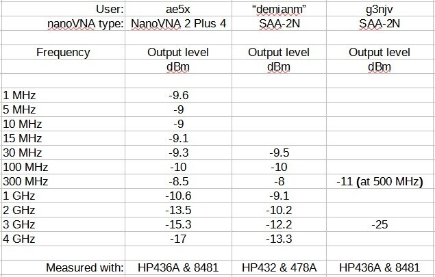
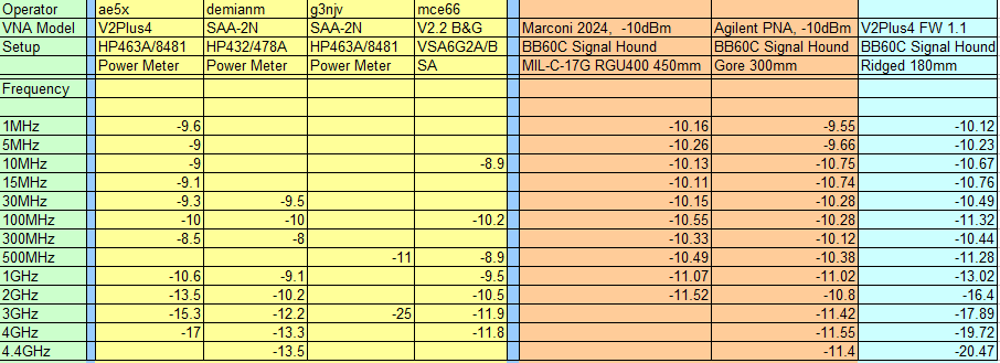
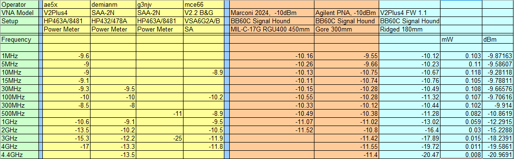
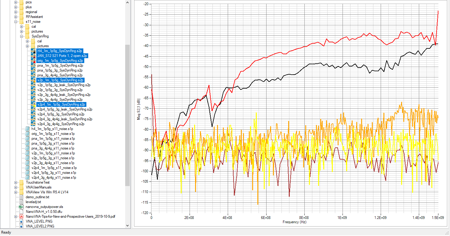
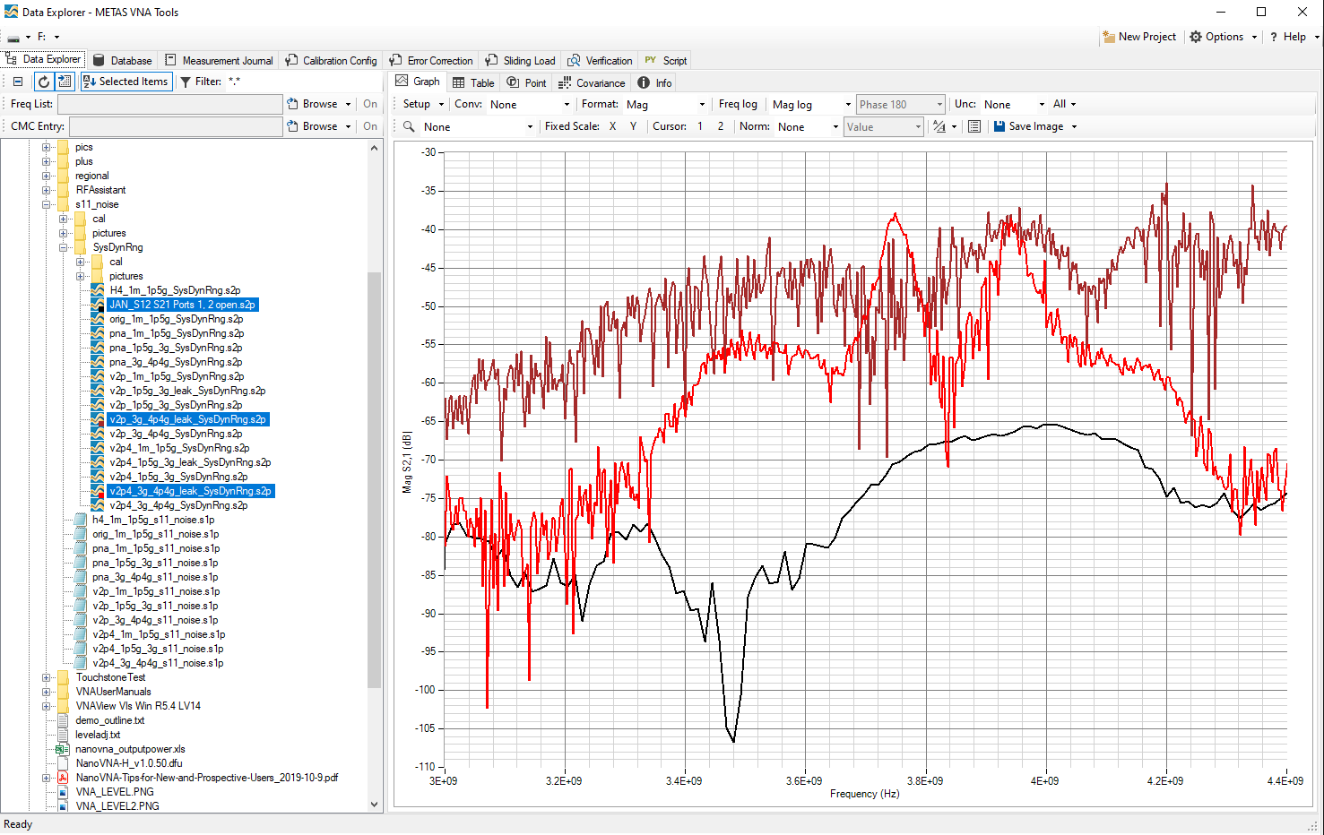
I found the max O/P level @500MHz around -11dBm and @3G it was -25dBm. Just these two levels, nothing in between right across the range.
Using menu commands to alter output level has no effect, the O/P level does not change - at all!
I'm using an HP436A power meter with HP8481 head. This cals up nicely at 50MHz.
Has anyone else measured their VNA output power?
Is the lack of output level control a firmware issue?
Is the O/P level I am measuring typical or do I have a faulty unit, or a faulty power sensor head?
I would have thought -25dBm pretty low, seriously affecting measurement dynamic range.
Any help/comment/advice welcome.
Thanks, Paul G3NJV

OwO 2021/10/26 20:42

Normally it's fine for the amplitude to drop off a little at the upper frequencies, but from -11dBm to -25dBm is huge and points to an issue with the baluns. Since the baluns specified on the old V2 design is EOL and compatibles cost more, clones have been using baluns rated to much lower frequency limits. This will also affect measurement noise and -30dB S11 noise floor is considered huge (the official specs are -40dB right after calibration).

Lex PH2LB 2021/10/26 23:30

This are the output values around 30MHz (measured them once when I wanted to sort out a large lot of crystals)

* CH0 output V2 : -6.1 dBm
* CH0 output org : -4.1 dBm
* CH0 output H4 : +6.2 dBm

Will make a few other measurements on higher frequencies and post them her.

73 to you and yours.

Lex PH2LB

demianm_1 2021/10/27 11:16

I also have an SAA-2N. I just checked it in CW using an HP432A + 478A
30 MHz       -9.5 dBM
100 MHz   -10.0 dBM
300 MHz     -8.0 dBM
1 GHz          -9.1 dBM
2 GHz        -10.2 dBM
3 GHz        -12.2 dBM
4 GHz -       13.3 dBM
4.4 GHz     -13.5 dBM
I did not do the full corrections but these should be enough to validate the basic performance.
This seems in line with what to expect. Mine seems to have some other bugs, like storing calibrations and recalling them but maybe I just need to RTFM in more detail to get it right. I do not have a counter that goes over 100 MHz so I cant confirm those higher numbers are what they seem.

mce66 2021/10/27 12:54

I measured levels on my Nano v2.2 version (an "old" clone).
Look at this message ( https://groups.io/g/NanoVNAV2/message/1867?p=%2C%2C%2C20%2C0%2C0%2C0%3A%3Arecentpostdate%2Fsticky%2C%2CdBm%2C20%2C2%2C0%2C83327507 ).
Best Regards.

Joe Smith 2021/10/27 17:07

On Wed, Oct 27, 2021 at 11:30 AM, Paul Randall G3NJV wrote:

>
> Using menu commands to alter output level has no effect, the O/P level
> does not change - at all!
> ...
> Is the lack of output level control a firmware issue?

I don't have your model but I tried to look into why I could not change the power levels on the V2Plus4.   The firmware was a bit of a mess.  There are comments that contradict other comments and nothing is in the interface document.  I have software that attempts to program these registers but had no luck getting anything to work and assumed the firmware just never supported it.

OwO 2021/10/28 03:23

-13dBm is probably OK, but OP's -25dBm is way out of spec and leads to the high noise shown in this comparison: https://nanorfe.com/images/v2_comparison.png

Make sure to check the official website https://nanorfe.com/nanovna-v2.html for where to find original units and how to avoid a bad clone.


________________________________

Joe Smith 2021/10/28 05:08

>
> -13dBm is probably OK, but OP's -25dBm is way out of spec

I don't see where the output level is covered in the specs or the FAQ.   It seems even -13dBm is borderline.  Are there any official numbers published for the products your company produced?

OwO 2021/10/28 12:32

By design it is -7dBm to -10dBm typical. However the production QC is gated on SNR, not output power, so there are no hard specs. On older designs (all except plus4), there were always about 5-10% of baluns that fail the test and have to be replaced, but if you got a clone with no QC you could get one with a bad balun and end up with high noise.
________________________________

Stephen Laurence 2021/10/28 07:45

Dear owo and all other readers,

Regarding the comparison of three saa2 devices, the noise on the Smith chart for the “clone” ssa2-N is cured by additional tantalum capacitors on the board, but in particular on the display board. The 4” screen pulls pulses of current which results in the “noisy” display.

I am very satisfied with my three saa2-N devices, especially after adding capacitors in a couple of places and fixing (with Gaffa tape) Laird ferrite plates on the board to reduce rf leakage (makes a significant improvement to dynamic range). The only disadvantage is that the device is then a bit heavier!

Steve L. G7PSZ

Siegfried Jackstien 2021/10/28 19:16

yepp ... i second that ..

nearly all clones behave similar after a few caps here and there are added

and yes some damping between the ports helps to reduce leakage

dg9bfc sigi

Am 28.10.2021 um 16:45 schrieb Stephen Laurence:

Nels Nelsen 2021/10/28 11:08

You mention you made changes to your vna by adding capacitors and I am looking for specific  values and placements in past postings. I have not found the information. As I must take apart mine soon could you please help me with the best placement?

Thank you,
Nels

Karl Jan Skontorp 2021/10/28 11:39

Is this what you can call a noisy measurement?
I have measured the output level (CW-mode) with a SA, it shows a level of -23dBm one the "CW frequency" and then a lot of harmonics. There is something wrong with my device as the unit worked correct. I don't know what is wrong with it.
Karl

John AE5X 2021/10/28 12:27

I made some measurements today at various frequencies. Included are the measurements of others posted here:

demianm_1 2021/10/28 12:35

I would appreciate some documentation on this. It seems pretty straightforward however a few pictures and notes would help. Also, which firmware are you using on the SAA-2N?

Karl Jan Skontorp 2021/10/28 13:20

My SAA2-N is not showing nice measurements anymore. I don't know what has happened, the displayed measurement just changed from one day to the next.
Is the attached picture what you can call a "noisy display"?
Karl

Joe Smith 2021/10/28 15:58

After a half hour warmup, used my RF generator and old VNA to get some idea on the error.  Both were set to -10dBm and measured with my Signal Hound BB60C.  Then measured the V2Plus4.

I've had the V2Plus4 for some time. It still has the original 1.1 FW installed.

Joe Smith 2021/10/28 18:31

I have a cheap power meter that I also tried with the V2Plus4 and ended up with roughly the same results so seems that the data is at least in the ballpark.    -20dBm is a long way off from the typical -7 to -10dBm.   This V2Plus4 was purchased directly from your store.  I suspect it's normal.

OwO 2021/10/29 04:17

The -7dBm to -10dBm figure is for the older V2.2/V2.3 designs. The V2Plus4 has a new patented reflectometer design that does not use baluns, and the output power is about 5dB lower. It is not important though, the only thing that really matters is the SNR, which is easy to see from the smith chart.
________________________________

OwO 2021/10/29 04:25

Karl Jan Skontorp: this one is probably caused by static damage.


________________________________

Joe Smith 2021/10/29 16:54

On Fri, Oct 29, 2021 at 12:17 PM, OwO wrote:

>
> The -7dBm to -10dBm figure is for the older V2.2/V2.3 designs. The V2Plus4
> has a new patented reflectometer design that does not use baluns, and the
> output power is about 5dB lower. It is not important though, the only
> thing that really matters is the SNR, which is easy to see from the smith
> chart.

Thank you for the update.  I see where you specify something for S11 noise floor.  Can you also please provide details on how you make this measurement?   Are you using the peak, average, RMS?    Any idea on the expected performance above 3GHz?   If you have a documented procedure that you use in production to test them, maybe a few of us could also compare results.

Joe Smith 2021/11/01 05:54

To measure the S11 noise floor,  I used the standard cal kit that was provided with the V2.  The standards were connected directly to the VNA's ports (no cables or adapters were used).  Standards were properly torqued.   Three different bands were used, 1MHz - 1.5GHz, 1.5GHz-3GHz and 3GHz - 4.4GHz, calibrating for each band.    For comparison the original NanoVNA and H4 were also measured in the 1MHz to 1-5GHz band.

The V2P and V2P4 were purchased directly from OWO's site.   These are specified to -50dB below 1.5GHz and -40dB below 3GHz.  There are no specifications that I found for working above 3GHz.  They do not specify how this data is collected.  The data presented was not altered.  I appears that even the peak levels would easily meet their spec.

I have not done anything with the H4 since purchasing it but it's interesting how up to about 300MHz it has lower noise.

Douglas Griffin 2021/11/01 09:20

Nice work Joe! Great explanation and presentation of both unit’s performance across their bandwidths.

Thank you!

Doug WA1KRX

Joe Smith 2021/11/01 17:38

The specs for the System dynamic range for the V2P is 60dB < 3GHz and 70dB < 3GHz, without averaging.  I will assume System mean no amplification.   As before, the standard cal kit that was provided with the V2 was used.  The standards were connected directly to the VNA's ports.  For the thru, a single cable was attached from port 1 to 2.   I used one of the blue cables supplied with the V2P.  A;; connections were properly torqued.   Three different bands were used, 1MHz - 1.5GHz, 1.5GHz-3GHz and 3GHz - 4.4GHz, calibrating for each band.   Both ports were terminated to 50 ohms when making the measurement.

I used my software to make all of these measurements.  The ideal model was used in all cases.   My software supports the leakage term.   When measuring above 3GHz, I show it with and without the leakage term.

Assuming they use the peak data, both Plus models appear to marginally meet the standard.  It's very impressive what all of these are capable of.

Looking forward to seeing the V3.

Joe Smith 2021/11/04 18:08

Someone with the Jankae VNA had posted the data for theirs.   It appears to do some sort of filtering above 3GHz were I am providing the raw data from the others.

https://github.com/jankae/LibreVNA

Joe Smith 2021/11/06 19:44

Looking at the firmware for V2P,

int main(void) {
bool shouldShowDmesg = false;
...
//    -- 40: average setting
//    -- 41: si5351 power (reserved)
//    -- 42: adf4350 power
registers[0x40] = current_props._avg;
registers[0x41] = current_props._si5351_txPower;
registers[0x42] = current_props._adf4350_txPower;

So maybe 0x42

/*
For a description of the command interface see command_parser.hpp
-- register map:
-- 00: sweepStartHz[7..0]
-- 01: sweepStartHz[15..8]
......
-- 30: valuesFIFO - returns data points; elements are 32-byte. See below for data format.
--                  command 0x14 reads FIFO data; writing any value clears FIFO.
-- 40: adf4350 power
-- 41: si5351 power (reserved)
-- 42: average setting

So maybe 0x40

static void cmdRegisterWrite(int address) {
if(address == 0xee) {

...
}
if (address == 0x40) {UIActions::set_averaging(registers[0x40]); return;}
if (address == 0x42) {UIActions::set_adf4350_txPower(registers[0x42]); return;}

if(!usbDataMode)

So maybe 0x42...

// the parameters for one point in the sweep
struct sys_sweepPoint {
...
// populated with 3
uint8_t adf4350_txPower = 3;

// populated with 1
uint8_t si5351_txPower = 1;

Maybe hard coded to max power level +5.   Sadly, it's not documented.

Attempting to change the ADF4350 with the provided QT software doesn't do anything.

To reply to this topic, join https://groups.io/g/NanoVNAV2

View this thread on groups.io