Beware of cheap underperforming clones

As of 2022 there are many badly performing clones on the market. V2/3GHz NanoVNA uses parts like ADF4350 and AD8342 which are costly and clones have been cutting costs by using salvaged or reject parts.

See official store and look for V2 Plus4/V2 Plus4 Pro versions only to avoid getting a bad clone. We have stopped selling V2.2 versions since October 2020, so all V2 hardware that are not Plus or Plus4 are not made by us and we can not guarantee performance.

NanoVNA V2 Forum

Note: this page is a mirror of https://groups.io/g/NanoVNAV2.
Click here to join and see most recent posts.

V2plus4 Problems in Low-Frequency Narrowband Measurement


Tenko46T 2020/11/28 04:22

Hello, everyone

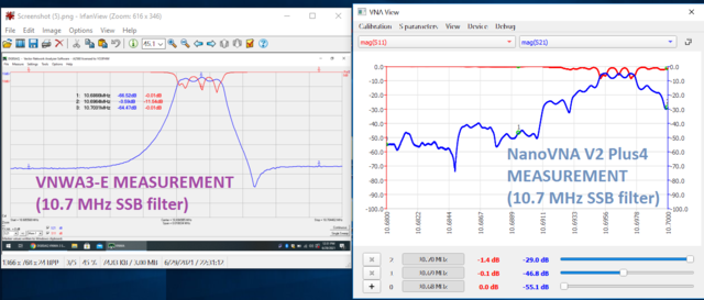
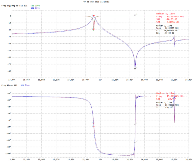
Yesterday I received NanoVNA V2plus4 from DHL which I was looking forward to. Unfortunately, when I measured the 10.7 MHz monolithic crystal filter S21, there was an abnormality in the waveform, so I would like to report it. Attach the same filter results as measured with V2_2 and V2plus4. The waveform of V2plus4 is jagged and not smooth. This does not happen with V2_2, so I think it is the problem of the V2plus4 which I purchased. This phenomenon appears to be frequency dependent and did not occur with the 20 MHz crystal S21. I tried making and replacing the latest version of the git -20201124 firmware, but it was still the same. Waveform errors are the same for stand-alone operation or controlled by NanoVNA-App v 1.1.160 via USB.
I hope this problem will be resolved.
--
TENKO

OwO 2020/11/28 22:31

It's a known issue: https://nanorfe.com/nanovna-v2-faq.html

"the V2 is not suited to very narrowband measurements (coherent
bandwidth <1kHz) because of the fast switching of the transmit and
receive paths. In practice this only becomes a problem when measuring
crystals (not SAW filters)."

amirb 2020/11/28 06:51

his measurement span is about 80KHz (or was it 100KHz?) so it is not <1KHz

however, if by "Coherent BW" you mean Resolution BW (IF filter), then the usefulness of this device is very limited if it cannot properly work for RBW <1KHz

i'd rather have a slower sweep than not being able to measure in a 100KHz span

Stephen Laurence 2020/11/28 07:35

Well, an opportunity to clear some confusion in my mind, please.

The resolution bandwidth is not controllable on the official v2 series firmwares, but the excellent version from Japan had an option of resolution bandwidth down to 100hz as far as I can remember.  When I compared the two firmwares, the effect of small rbw on noise floor and trace jitter was similar to increasing the averaging (which is also controllable on the Obijan firmware).

Does the Obijan firmware jitter or sweep the actual baseband frequency about (using fft I presume) or is it not real? Can you measure crystals with the Obijan software, because if it is possible, I will leave one of my v2 devices unmodified and on the Japanese firmware.

It would be a real pain to have to get out my noise generator, homemade bridge and fire up a Boatanchor spectrum anayser if I have to tweak narrow band crystal filters ever again, but at least I would be forwarned.

Steve L. G7PSZ

Tenko46T 2020/11/28 15:07

Thank you for your reply. ​I am very happy to hear from the developers directly.

​It was a known problem in V2. ​I'm sorry to bother you.

​However, I would like to tell you that the V2_2 I purchased in August did not have this problem.

​I'm sorry to be asking but this may be a problem specific to my V2 Plus 4. ​For example, DDS may not be in time for frequency hopping, or the jitter of the reference oscillation may be very bad.

​If it is not a specific problem, is it because of the circuit constant change made in the sweep speed and the AGC acceleration which are one of the differences between V2 Plus4 and V2_2? ​For example, when the gain is switched, charge is injected from the gate of MOS transistor, and the waveform of IF may change.
--
TENKO

Tenko46T 2020/11/28 15:24

​Thank you for your reply.

​I know that the Ojisan firmware uses CIC filters to implement RBW variably.
​I understand the importance of narrowing the RBW for narrowband measurements like crystal filters, but the Ojisan firmware does not seem to support V2plus 4 yet, so I am sorry but I cannot implement and verify it.

​I am also hesitant about the high-speed sweep modification of V2_2. ​Until this problem is resolved, it is likely that Ⅰ will be using two different V2's depending on the purpose.
--
TENKO

Tenko46T 2020/11/28 17:28

In response to your request, I installed Ojisan firmware 20201004 on my V2_2.
​Attached is the result of X'tal filter with F0 = 10.6935 MHz BW = 2.2 kHz measured with V2_2 set to RBW = 100 Hz, SPAN = 10kHz.

Since this graph does not convert the reference impedance from 50 ohms, the waveform is not correct. However, if the reference impedance is converted to 500 ohms, the insertion loss is reduced to about 4 dB, and the passband is slightly flatter.

​Then, changing RBW = 1 kHz and AVG = x10 instead produced a similar waveform.
​I hope this helps you.
--
TENKO

OwO 2020/11/29 11:34

Measuring crystals isn't supported on any V2, even if the curve looks
smooth it's still wrong. I recommend using a V1 NanoVNA to measure
crystals. I will try to fix this in a later firmware update that allows
you to select the wait time and integration time (and thus VBW).

Tenko46T 2020/11/28 20:59

​Thank you for a positive answer. ​I am looking forward to the firmware update. ​
​As you said, I understand that even if it looks smooth, it cannot be measured correctly.

​It is surprising that V2 implements VNA with only one AD converter and the interrupt processing on GD32 can sample R, A and B at the correct timing.
​Moreover, if the V2plus4 is changed IF frequency higher than V2_2, I imagine that the phase change for timing error is large and severe.

​Gabu-chan, Thank you very much this time.
--
TENKO

Stephen Laurence 2020/11/29 00:35

And thank you both for partially answering my question(s). I am still slightly muddled, but I will proceed to upgrade one of my v2 machines (V2N, my favourite) to plus, as it is reversible, with a soldering iron and firmware restoring.

I also have an original v1-H which I can turn out if needed. At present, it is the loan machine, but I will promote it to “first backup”.

Steve L

John Gord 2020/11/29 16:41

I have obtained good results on my -V2 (consistent with my 8753D) on crystals using the osijan firmware.  For a 1kHz wide sweep at 26MHz I used either RBW 10 Hz, AVG 1 or RBW 1kHz, AVG 50.  Either setting gives a slow sweep, but that is what is needed for a narrow resonator.

--John Gord

Tenko46T 2020/11/29 17:31

​Wow, really!
​The V2 Ojisan firmware works with the same RBW as the 8753 D. ​Your V2 is great. ​Is my V2 okay?
--
TENKO

John Gord 2020/11/29 21:18

TENKO,

As far as I can tell, the Ojisan firmware works on the 2.8" and 4" display versions of the NanoVNA-V2, but probably not the V2plus or V2plus4.  There are different files for the 2.8" and 4" versions, of course.
He also has a version for the original NanoVNA-H, but because of limited memory it does not have all the features.

--John Gord

On Sun, Nov 29, 2020 at 05:31 PM, Tenko46T wrote:

Tenko46T 2020/11/30 00:48

Thank you. John,

I have both V2_2(2.8") and V2plus4, and at the moment V2plus4 does not support narrow band measurement, but if I put Ojisan firmware in the V2_2 and set RBW to small, I may get the same measurement result as 8753 D.

​This is a good news. ​In fact, I used to measure crystal filters using HP8640B's FM external modulation and HP8754, but they were both old and heavy, and I disposed of them because I thought my workbench would be in danger in case of a big earthquake.
--
TENKO

Stephen Laurence 2020/11/30 01:06

All the above is well worth knowing.

I will keep at least one of my (soon to become antique) v2 devices on Ojisan software. I can get passable results up to 4ghz on two of my v2 and can increase the dynamic range somewhat by attaching little ferrite plates around the circuit board. They are various sizes 1-2cm and 2mm thick but I can buy 40 of them on Ebay for £8 - much less than a single Ferrite emi sheet.

I have used the through stripline on the block of four attenuators (£5 Ebay) to assess the attenuation of various materials connecting it between port 1 and 2 with a 0-4gkz sweep and logmag on 2db per division. Attenuation over a stripline is a measurement some of the emi manufacturers use.

When placed over the 2cm of stripline, a ferrite plate attenuates the signal zero at 1mhz increasing to 7db at 4ghz. This seems to be better attenuation than the emi manufacturers’ results of their most expensive emi absorbers which cost more than a V4 for one sheet.

Steve L

Thorsten DL9SEC 2020/11/30 03:14

Hi,

could you please clarify, what the "Ojisan" firmware is?

Tnx.

73, Thorste DL9SEC

amirb 2020/11/30 04:31

same question here

does it work on SAA-2N from deepelec?

Tenko46T 2020/11/30 06:01

Click the link below to download Ojisan firmware to your PC immediately.
​If you have trouble downloading, delete the "? dl = 1" at the end of the link.

​Firmware for 4-inch LCD (ST 7796) NanoVNA-V2.
https://www.dropbox.com/s/vwomqt986wkel2b/binary_st7796_20201004.bin?dl=1

​Firmware for 2.8 inch LCD (ILI 9341) NanoVNA-V2.
https://www.dropbox.com/s/g648ut5fqkajq4q/binary20201004.bin?dl=1

​I remember that Ojisan firmware was mentioned in another Groups.io before. ​Please refer to this.
https://groups.io/g/NanoVNAV2/topic/firmware_from_ojisankoubou_in/76854966?p=,,,20,0,0,0::recentpostdate%2Fsticky,,,20,2,0,76854966

--
TENKO

amirb 2020/11/30 06:20

does this work on SAA-2N?

thanks

Stephen Laurence 2020/11/30 06:24

Yes. Very well. However I have removed it as I will be converting to v2plus soon and it does not work on v2plus unfortunately.

I still have it on several of my others, however. It is easy to load and change firmwares, anyway, especially if you keep the various firmwares archived on your computer.

Steve L

hwalker 2020/11/30 06:49

On Mon, Nov 30, 2020 at 06:20 AM, amirb wrote:

>
> does this work on SAA-2N?
>
>

If your SAA-2N has a floating point unit then it will work.  Some early production units may not.  Check Config->Version and "Has FPU:" must be marked "yes".  There may also be a couple of bugs in the firmware that you may need to work around.  S21 measurements may have an ~1.5 dB offset due to the BBGAIN 3 value in the SAA-2N being -18.5 instead of ~-20.0.  Long marker drags using a stylus may also cause the SAA-2N to lock-up and require re-booting.

The author has also said that he no longer intends to support the firmware so no future improvement to the firmware maybe forthcoming unless he changes his mind.  One feature that will soon become available on other firmware is the ability to take screen shots, which is great for documenting measurements instead of having to take photos.

- Herb

amirb 2020/11/30 06:57

On Mon, Nov 30, 2020 at 09:49 AM, hwalker wrote:

>
> On Mon, Nov 30, 2020 at 06:20 AM, amirb wrote:
>
>> does this work on SAA-2N?
>>
>>
>
> If your SAA-2N has a floating point unit then it will work.  Some early
> production units may not.  Check Config->Version and "Has FPU:" must be
> marked "yes".  There may also be a couple of bugs in the firmware that you
> may need to work around.  S21 measurements may have an ~1.5 dB offset due
> to the BBGAIN 3 value in the SAA-2N being -18.5 instead of ~-20.0.  Long
> marker drags using a stylus may also cause the SAA-2N to lock-up and
> require re-booting.
>
> The author has also said that he no longer intends to support the firmware
> so no future improvement to the firmware maybe forthcoming unless he
> changes his mind.  One feature that will soon become available on other
> firmware is the ability to take screen shots, which is great for
> documenting measurements instead of having to take photos.
>
> - Herb
>

thanks for the valuable info
mine does have FPU but those bugs dont sound good

hwalker 2020/11/30 07:14

On Mon, Nov 30, 2020 at 06:57 AM, amirb wrote:

>
> thanks for the valuable info
> mine does have FPU but those bugs dont sound good

Not all SAA-V2N's experience the bugs.  As Stephen said, it is easy to change firmware, so if you don't notice the bugs you are good to go.  If you do, then it is easy enough to change back to your previous firmware if you decide the bugs are too annoying and outweigh the other nice firmware features.

If you do load the firmware, check Config->DMSEG and if BBGAIN 3 value is ~-18.5dB then you will most like have the 1.5dB S21 offset error when measuring attenuation values greater than 10dB.  The long marker drag lockup bug can be worked around by using the buttons instead of the stylus to move the markers.

- Herb

- Herb

Siegfried Jackstien 2020/11/30 17:44

set adf4350 power down to 0 or 1 ... save in slot 0 .. switch off and on
again ... now recheck bb3 gain ... should be very close to 20 db

thats what i found out here ... a bit lower clock power and the
calibration at startup works better

on high power i have seen 19.75 or 19.85 ... but with lower power i see
more or less exact 20 db (19.96 to 19.98)

dg9bfc sigi

Am 30.11.2020 um 15:14 schrieb hwalker:

DiSlord 2020/11/30 10:21

Most simple way for solve BBGAIN3 issue (if BBGAIN3 ~ -18.5, it come from bbgain0 overflow due to strong output power) is set STIMULUS->GFG SWEEP->ADF 4350 TX POWER set to 0 and save to 0 slot

After device powerup it should load this setting and correct calibrate BBGAIN.

After you can increase ADF 4350 TX POWER to 3

PS i suggest autoset ADF 4350 TX POWER to 0 on bbgain calibration, but at this moment this fix not added....

hwalker 2020/11/30 12:01

On Mon, Nov 30, 2020 at 07:14 AM, hwalker wrote:

...  If you do load the "Ojisan" firmware, check Config->DMSEG and if BBGAIN 3 value is ~-18.5dB then you will most like have the 1.5dB S21 offset error when measuring attenuation values greater than 10dB.  The long marker drag lockup bug can be worked around by using the buttons instead of the stylus to move the markers.
========================================

It's been a while since I tried the "Ojisan" firmware and couldn't remember if it allowed setting the the ADF4350 power level.  If it does, and your BBGAIN 3 value after upgrading is ~-18.5dB then you should be able to correct the S21 offset error by following the suggestions of Sigi and DiSlord.

- Herb

Stephen Laurence 2020/11/30 12:56

On Mon, Nov 30, 2020 at 12:31 PM, amirb wrote:

Stephen Laurence 2020/11/30 12:57

Yes, as long as you chose the one for the 4” screen, otherwise the screen js white. If that happens, just load the other one.

Steve L

Tenko46T 2020/12/06 00:24

Hi Steve,

Thank you for your advice on wave absorbers.

In the V2Plus4, the ferrite sheet as OwO said was used.
https://groups.io/g/NanoVNAV2/message/294?p=,,,20,0,0,0::relevance,,material,20,2,20,76323797
I found the ferrite sheet in the same picture is sold at the following site. It seems that I can buy it at a relatively reasonable price.
https://www.chinahao.com/product/4033059171/

Nicolson-Ross-Weir method is well known for its complicated permeability, but it is difficult because it requires the attachment of a coaxial line.
I think it is practical to use the microstrip line as you say.

However, I was surprised that OwO put a ferrite sheet in a microwave oven and examined its performance.
I felt the scales come off my eyes.

--
TENKO

Siegfried Jackstien 2020/12/06 11:49

put it in microwave ... if it heats up in a second or two its lossy at
13cm (put a cup of water also in the oven that it has some load)

and you need a material that is lossy in that area

the microwave oven maybe is not the best test ... the stripline method
is not much better

best maybe would be a cavity test (two probes in a cavity and measure
with and without sheets on the walls) cause we wanna surpress
reflections from the walls

greetz sigi dg9bfc

Am 06.12.2020 um 08:24 schrieb Tenko46T:

Tenko46T 2020/12/06 04:58

Cavity tests include reflection effects and require careful analysis to obtain correct results. It is important to convert the energy of electromagnetic waves into heat, not reflection.

The complex term of permeability contributes to the loss. I thought the microwave oven method was wonderful because it was full of amateur spirit to select such materials quickly.

By the way, water is not a magnetic material but a dielectric material. However, the complex term of the dielectric constant reaches its maximum at about 20 GHz, and even at 2.4 GHz, there is a loss, so it is suitable for cooking because the electromagnetic wave penetrates inside moderately and generates heat.
--
TENKO

Siegfried Jackstien 2020/12/06 13:18

Am 06.12.2020 um 12:58 schrieb Tenko46T:
> Cavity tests include reflection effects and require careful analysis
> to obtain correct results. It is important to convert the energy of
> electromagnetic waves into heat, not reflection.
yepp ... if signal goes down the wave is absorbed in the cavity ... to
compare different meterials .. set 0 db without sheet and then add them
inside ... lowest signal is best material to use
>
> The complex term of permeability contributes to the loss. I thought
> the microwave oven method was wonderful because it was full of amateur
> spirit to select such materials quickly.
cooking sheets is a fast test yes ... to compare ... heat all sheets at
once in the oven ... hottest sheet after a few seconds of cooking is
best :-)
> By the way, water is not a magnetic material but a dielectric
> material. However, the complex term of the dielectric constant reaches
> its maximum at about 20 GHz, and even at 2.4 GHz, there is a loss, so
> it is suitable for cooking because the electromagnetic wave penetrates
> inside moderately and generates heat.
and that is why you should not dry your wet pet (dog, cat, hamster) in
your microwave ... it penetrates to deep ... grin

Bobinuta Bobinel 2021/06/30 13:29

Good evening,
My old father asked me to help him to play with some crystals and to find him a solution to build his own SSB filters.
I already have a VNWA3-E from 2014, but as I expected, he wanted his own device... so I started to look for different hobby VNA solutions; the NanoVNA seems to be a good start. So, I ordered a NanoVNA V2 Plus4 on 04/04.2021 and after 73 days, I managed to pick it up (on 17Jun2021).

Before buying the device, I read the disclaimer on the site, the one that OwO quoted here: " the V2 is not suited to very narrowband measurements (coherent bandwidth <1kHz) because of the fast switching of the transmit and receive paths. In practice this only becomes a problem when measuring crystals (not SAW filters) " .
However, I found the topics about Ojisan firmware and that was the trigger that made me to buy the full metal version of the NanoVNA V2 Plus4 (yes, the 153 USD one).
I mean, the hope that Ojisan firmware will work on a NanoVNA V2 model.

Well, now I am *very* dissapointed, because of the same problem as Tenko. See the attached photo.
And the Ojisan's firmware does not work on NanoVNA V2 Plus4. I tried two .bin files, without any luck. After firmware upload, no reboot occured and the LCD became white. I returned to the last official firmware, the device works again, but all my hopes are distroyed now. And also, the last hope to bring back again the smail on my father's face ...

I am sure that me and Tenko are not alone, so I would like to kindly ask Mr. OwO about his intentions, if he can estimate (at least approximately) a date when he thinks that he could offer the first version of the firmware with which crystals could also be measured ?

In the hope of a professional answer, please allow me to congratulate you for the big work on NanoVNA and to wish you all the best !

Best regards,
C.

Esteban H 2021/06/30 22:23

Why is so irregular the picture on the right?

Is it about 3 KHz bandwidth centered in 10.696 MHz?

What is the minimum resolution bandwidth of the instrument to have a smooth
curve?

Is that the expected behaviour with the instrument out-of-the-box or it was
due to a firmware update that did not work?

(mine is on the way 🤔)

Thanks

El mié., 30 jun. 2021 21:29, Bobinuta Bobinel via groups.io <bobinuta=
yahoo.com@groups.io> escribió:

Siegfried Jackstien 2021/07/01 02:07

go and buy an old nanovna ... not v2 or v2plus or v2plus4

that is better on low frequency

....

or use ojisan fw in a v2 but not on v2plus4

greetz sigi dg9bfc

Am 30.06.2021 um 22:29 schrieb Bobinuta Bobinel via groups.io:

OwO 2021/06/30 20:04

Always refer to the official documentation. There is quite a bit of misleading or outright wrong information in other groups and I can't respond to all of them, so treat anything you read about the V2 outside of this group and the website as false. It is *not* possible to measure crystals with *any* firmware version. Some firmwares might have used slower switching but that doesn't fix the settling issue, it only covers it up. So with some firmware it might *appear* to measure crystals fine but will give the wrong measurement results. Unofficial firmwares are also very out of date with the latest firmware changes (required to support the hardware changes), so I recommend sticking with firmware versions listed on the nanorfe.com website.

I do have plans to add support for measuring crystals in the V2 Plus4 firmware but right now I'm very busy with other projects and V3, so it may take some time.

Esteban H 2021/07/01 04:37

But, what is the minimum distance in Hz between two consecutive samples to
have a smooth curve in a, let us say, 6 order LC Chebyshev filter?

I am understanding that may be problems with whatever peak in the
transference curve that is in the order of kHz, but what is the minimum
order if magnitude to work with?

Thanks


El jue., 1 jul. 2021 4:04, OwO <OwOwOwOwO123@outlook.com> escribió:

OwO 2021/06/30 21:55

Frequency resolution is 10kHz. The mentioned problems only happen when the bandwidth of the DUT is much smaller than this.

Esteban H 2021/07/01 06:44

Thanks OwO.

Best Regards,
Esteban.

El jue., 1 jul. 2021 5:55, OwO <OwOwOwOwO123@outlook.com> escribió:

zeljko adzic 2021/07/01 08:07

Dear OwO nothing less important. a dot should be put on and.
I understand you, but it is also a priority for you to realize this. and I
look forward to that moment.
All the best


On Thu, 1 Jul 2021, 05:04 OwO, <OwOwOwOwO123@outlook.com> wrote:

Bobinuta Bobinel 2021/07/01 02:58

>> Esteban H: Why is so irregular the picture on the right?
>> Is it about 3 KHz bandwidth centered in 10.696 MHz?

Esteban, is nothing centered there.
I've been terrible disappointed to find out that neither VNA-QT or NanoVNA-Saver cannot offer some very useful functions as zooming into the bandwidth of the filter or moving the markers directly with the mouse. So, the only way to "zoom" is to see first a larger characteristic, then establish the new needed limits, make a new sweep setting and finally, a new calibration. That's horrible, eating a lot of time and nerves.
The images above just show a simple test I did to see how the filter transfer is displayed (a 5 crystals ladder for SSB).
The first sweep was larger, then I recalibrated for the second sweep, but I chose the wrong frequency limits - that is all. Nothing intentional :)
If the freq resolution is 10KHz minimum (as OwO said), i t is obvious why the characteristic on the right of my screenshot is irregular.
Is not irregular, is a totally mess !

>> Esteban:  Is that the expected behaviour with the instrument out-of-the-box or it was due to a firmware update that did not work?

Unfortunately, yes (for crystals, filters or other devices with narrow bandwidth).
One could ask me why I bought this NanoVNA V2 Plus4 ?
Simple answer: in the hope that the Ojisan firmware will run on it !
Unfortunately, on the Ojisan website I didn't find any useful disclaimer about differences between V2/V2 Plus and V2 Plus 4.
There is no warning written with bold&red fonts, to notify the users about the fact that the firmware doesn't work on V2 Plus 4 :((

So, take my observations as a tip for those who wish...

Esteban H 2021/07/01 13:13

Dear OwO,

After reading the nanorfe website, I understand that the 10 KHz resolution
limitation comes from the use of the chip ADF4350.

But nanorfe website also indicates that "additionally" there is a
limitation for low resolution that comes from a fast switching between the
Tx and Rx paths. Is this switching a hardware coded design (impossible to
change) or something that can be changed by firmware in the future to
eventually overcome that limitation?

(sorry for the questions, it is obvious I still has to read and research a
lot on this)

Thanks.

El jue., 1 jul. 2021 5:55, OwO <OwOwOwOwO123@outlook.com> escribió:

OwO 2021/07/01 13:26

Only devices with bandwidth < 1kHz are affected, and in practice it's physically impossible to build filters that narrow at > 10MHz. That's why I say it's only an issue when measuring crystals. It doesn't affect measuring SAW filters or any other filters. It is a firmware limitation which I have plans to fix.
________________________________

Esteban H 2021/07/01 14:36

Dear OwO,

Ok, understood. Let us see how it goes when arrive, I would like to make
something more than simple antenna adjustments (although plan to do this of
course), something more focused on filtering design and want to know the
limits. No Crystal filtering design envisaged at the moment anyway, or at
least not so selective.

Thanks and Best Regards,
Esteban.


El jue., 1 jul. 2021 14:26, OwO <OwOwOwOwO123@outlook.com> escribió:

Jim Lux 2021/07/01 06:49

On 7/1/21 2:58 AM, Bobinuta Bobinel via groups.io wrote:
> >> Esteban H: Why is so irregular the picture on the right?
> >> Is it about 3 KHz bandwidth centered in 10.696 MHz?
>
> Esteban, is nothing centered there.
> I've been terrible disappointed to find out that neither VNA-QT or
> NanoVNA-Saver cannot offer some very useful functions as zooming into
> the bandwidth of the filter or moving the markers directly with the
> mouse. So, the only way to "zoom" is to see first a larger
> characteristic, then establish the new needed limits, make a new sweep
> setting and finally, a new calibration. That's horrible, eating a lot
> of time and nerves.
> The images above just show a simple test I did to see how the filter
> transfer is displayed (a 5 crystals ladder for SSB).
> The first sweep was larger, then I recalibrated for the second sweep,
> but I chose the wrong frequency limits - that is all. Nothing
> intentional :)
> If the freq resolution is 10KHz minimum (as OwO said), it is obvious
> why the characteristic on the right of my screenshot is irregular.
> Is not irregular, is a totally mess !

Crystal filters with narrow bands are going to be difficult for
inexpensive analyzers like these to measure - There's a minimum step
size in the source, for instance - and that's an artifact of using a
single chip synthesizer.  There's also an effect from the receiver
filtering in the digital domain - if you collect 1 millisecond of
samples, you're not going to be able to have a receiver bandwidth less
than around 1 kHz, so that affects your SNR.

In a fancier analyzer, you might have

a) a multi loop synthesizer perhaps with a DDS to allow arbitrary, finer
steps

b) longer integration time at each step, to improve the SNR of the
measurement at each step.

c) longer time delay between applying the stimulus and making the
measurement - so devices with a lot of envelope delay are properly measured.

Some of these things can be addressed in firmware - but memory space is
a finite resource, and there's a lot of operational tradeoffs - And some
performance tradeoffs as well - collecting more samples from the
receiver over a longer time starts needs a better performing ADC (or ADC
sampling clock).

All of these small VNAs share some common aspects - they use "single
chip" low power building blocks (a great idea!) to make an inexpensive,
reasonably high performing device that runs off batteries for a
reasonable time - they pick features for the firmware that make them
usable "out of the box" for a lot of applications, if not optimized for
some use cases.   A NanoVNA (of any flavor) isn't a Keysight FieldFox.
But $100 and 100 grams is a lot different than $20k and 3kg.

It might be that to do the measurements a particular user wants, the
best solution is "wait for the next generation" or "buy the more
expensive box" or "design a specialized box"


DiSlord 2021/07/01 09:41

I made 1Hz resolution step on V2/V2Plus on < 140MHz (and variable resolution from 375Hz to 6kHz for ADF, depend from frequency range)
Also added correction for SI5351 output (as on H/H4), It is possible to obtain a very accurate output frequency with an error of only 1 Hz.

Bobinuta Bobinel 2021/07/01 10:22

On Thu, Jul 1, 2021 at 09:41 AM, DiSlord wrote:

>
> made 1Hz resolution step on V2/V2Plus on < 140MHz (and variable resolution
> from 375Hz to 6kHz for ADF, depend from frequency range)
> Also added correction for SI5351 output (as on H/H4), It is possible to
> obtain a very accurate output frequency with an error of only 1 Hz.

Good evening, Dislord!
Please enlight me:
1) have you released a firmware for NanoVNA V2 Plus4 , which may be used to measure crystals and narrow-band filters, such my SSB filter ?
2) if yes, where may I read details about it ? May I download it ?
Please tell me if you can help me with that, I will be grateful for your amability.
It is frustrating to buy an 150 USD device that cannot be used for such measurements ...

Thanks a lot,
Bob

DiSlord 2021/07/01 10:47

V2Plus4 not possible add this (by easy way)
As OWO say V2 not good for crystal measure (exist phase shift, this come from THRU gain compensation work)

Example measure 16M crystal on V2, as can see amplitude measure good, but phase shifted in some places (V2 not calibrated in this range, used interpolation)

Some measure vs disabled THRU gain compensation

As can see lost dynamic range (marker 2), but measure correct

Bobinuta Bobinel 2021/07/01 11:03

@DisLord, Owo, Jim Lux:

Crystal clear, gentlemen !
Thanks for the explanations and examples.
Well, it seems that to measure crystals and SSB filters, I will have to sell the current (brand new) NanoVNA V2 Plus4 device and until serious improvements appear, I will use NanoVNA V1 (standard edition edy555).
All this work, of course, for my father .

Best regards,
Bob

F1RVC 2021/07/01 20:09

Yes you are right , as OWO said , V2plus4 is out of time Did it be the
star one moment ? ... OWO is working on another source of money.... He left
V2Plus4 customers in the ......

Not interested with V2plus4 anymore as he said he did not have time anymore
for V2plus4.....


Le jeu. 1 juil. 2021 à 20:03, Bobinuta Bobinel via groups.io <bobinuta=
yahoo.com@groups.io> a écrit :

DiSlord 2021/07/01 11:21

Comparsion Crystal measure V2 and H4

Christian Cziezerski 2021/07/01 11:41

you’re being overly dramatic.

On Thu, Jul 1, 2021 at 11:09 AM, F1RVC wrote:

OwO 2021/07/01 19:30

Where did I say that? In fact I said there are plans to fix this in the official firmware. Do not frame me for things I did not ever say.

OwO 2021/07/01 19:34

To summarize:

1. All V2 versions are not suitable for measuring crystals at the moment, regardless of firmware. If you read otherwise in other forums it is wrong information.
2. There are plans to add support for this in the official V2 Plus4 firmware, but this will take a while as I have to make a living and work on other projects as well.

I think I answered all that there is to answer on this topic, so I'm going to lock this thread.

OwO 2021/07/01 19:47

Oh and if you think there's a problem with wanting to make a living, you need to reconsider your life choices. Don't be those white knights pretending to be all altruistic developing open source shit while e-begging on patreon by complaining on twitter nonstop about how hard life is and how they have to pay property tax on their $1M house they inherited from their parents, complaining about others trying to make a living, while not doing anything to try to better their own life. If you are seriously bored and have nothing to do maybe go watch some anime or something. I highly recommend Madoka Magica for the unenlightened.

OwO 2021/07/01 19:49

Gonna unlock this thread to see the hilarious responses I'm gonna get for that last post.

Stephen Laurence 2021/07/02 00:52

On Fri, Jul 2, 2021 at 03:49 AM, OwO wrote:

>
> Gonna unlock this thread to ........

No hilarious response, just disappointed that a previous icon of valuable contribution, sense and respect has sunk to the lower level of mud flinging and teddy bear throwing.

Steve L

OwO 2021/07/02 08:18

Never a bad thing to seek some entertainment.
________________________________

aleks07111971 2021/07/02 01:32

Don't be surprised if open source shit works better than your commercial projects! Everything is moving forward!
The niche of amateur devices is not rubber, you yourself got into the boat and jumped out of it yourself, and in the middle of the river! :)

OwO 2021/07/02 08:39

Got any evidence to back that up?
https://www.eevblog.com/forum/rf-microwave/nanovna-custom-software/msg3587475/#msg3587475
NanoVNA Custom Software - Page 45<https://www.eevblog.com/forum/rf-microwave/nanovna-custom-software/msg3587475/#msg3587475>
NanoVNA Custom Software - Page 45
www.eevblog.com


"From my experience with that first Nano, it became apparent that with it being opened source, a lot of people were interested in making their own changes to try and improve the firmware. It seemed like it would be a never ending battle to find something that worked well enough to use. It was bad enough that I put together a simple regression test to automatically check the firmware of the week. Much of the changes were focused on features I really had no use for rather than addressing the problems.

Not surprising, none of my vintage VNAs are open source. I'm not against it but when you have people making changes who really don't understand the problems they can cause, it's doing more harm than good. In the case of the original NanoVNA, having the source allowed a few people to address the basic problems and get it working. So there can be an advantage depending on the skills of the people working on it.

At least for these low cost VNAs, my demands for the firmware and hardware are simple. Document your code, allow the software to control what ever peripherals are attached and send down good data. Getting good data off the Nano was always a problem. Not because the protocol was complex or the PC lacks performance. It was just bad firmware. Oddly, more commands were added rather than correcting the root problems which had nothing to do with the protocol. Once the locals sorted out the basic problems, there was no need to do any more with it. I am surprised that much of what I saw with the early firmware is still a problem with the latest releases.

If people want to try and run my software with the original NanoVNA, the manual is pretty clear about different firmware/hardware combos being a problem. All the software in the world isn't going to make bad firmware/hardware good. We need a solid foundation to build on. "


Alright let's take this to private email, this has gotten off topic and spammy for everyone else on the list, so I'm locking the thread for good this time.
________________________________

To reply to this topic, join https://groups.io/g/NanoVNAV2

View this thread on groups.io