
DiSlord 2021/01/12 12:56
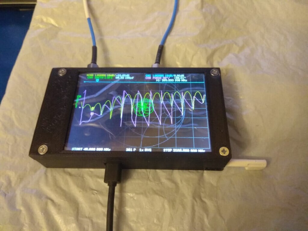
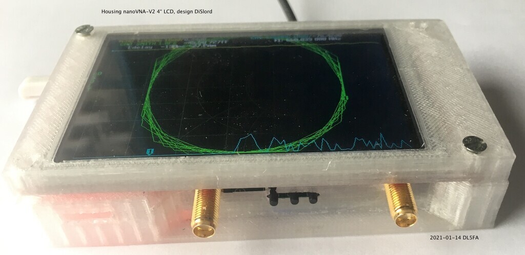
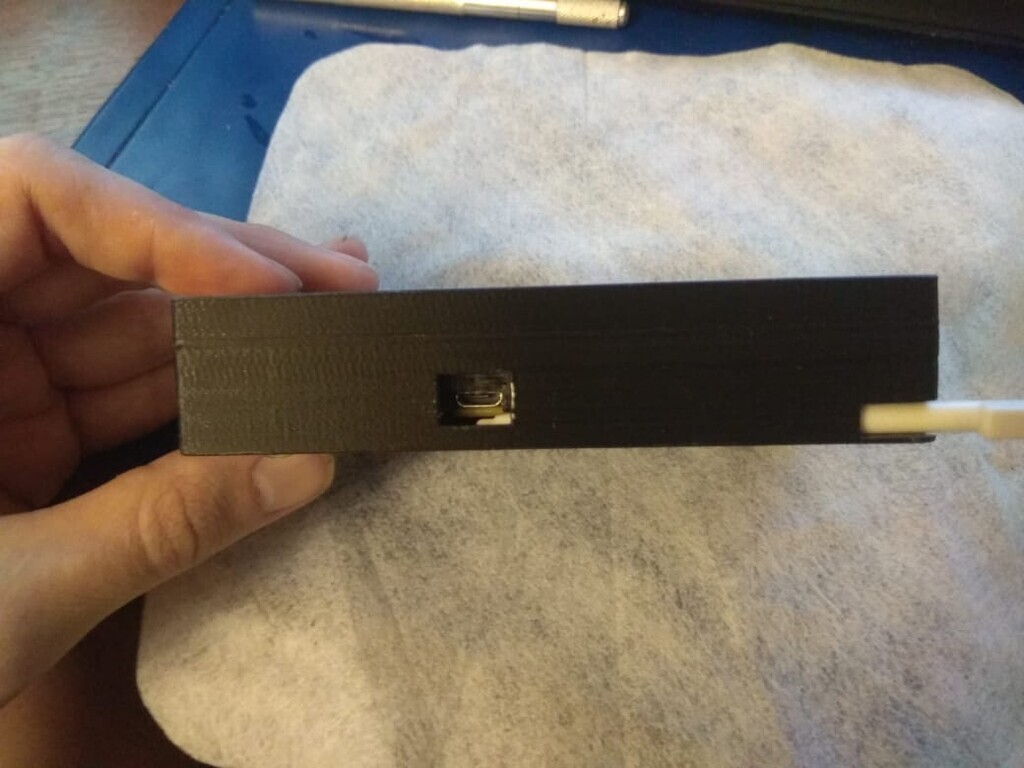
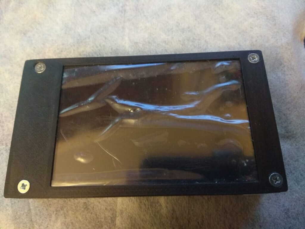
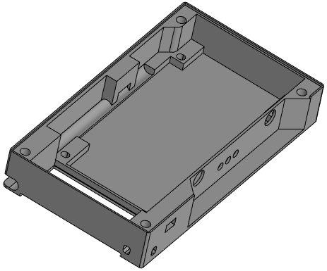
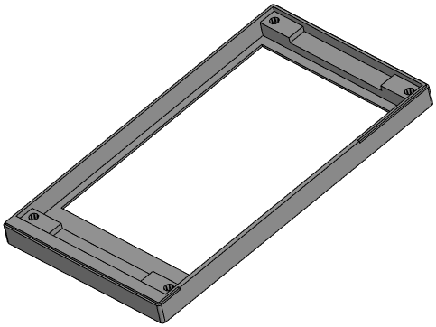
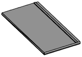
Made case for my V2 vs 4 inch screen
Possible add little storage for calibration kit inside
As of 2026 there are many badly performing clones on the market. V2/3GHz NanoVNA uses parts like ADF4350 and AD8342 which are costly and clones have been cutting costs by using salvaged or reject parts.
See official store and look for V2 Plus4/V2 Plus4 Pro versions only to avoid getting a bad clone. We have stopped selling V2.2 versions since October 2020, so all V2 hardware that are not Plus or Plus4 are not made by us and we can not guarantee performance.
Made case for my V2 vs 4 inch screen
Possible add little storage for calibration kit inside
Yes!:)
Nice case!
Dislord as you write firmware for the V2. Is there an issue with the V2plus4 with portions of the firmware not being open source? I thought I read a post from you about that concerning the boot loader? Trying to decide on an upgrade. Any info on the V3 that was in the works?
you got mail
dg9bfc sigi
Am 13.01.2021 um 00:15 schrieb Vince Rooney:
Thanks Siegfried!
Hello DiSlord,
Thank you very much for providing the .stl files for the 4 inch LCD housing.
Take care to turn the bottom part 180 degree in Z before rendering,
otherwise you get a lot of support printig.
As with each prototype, there are always things to improve.
Points for improvements (sequence with lowering importance):
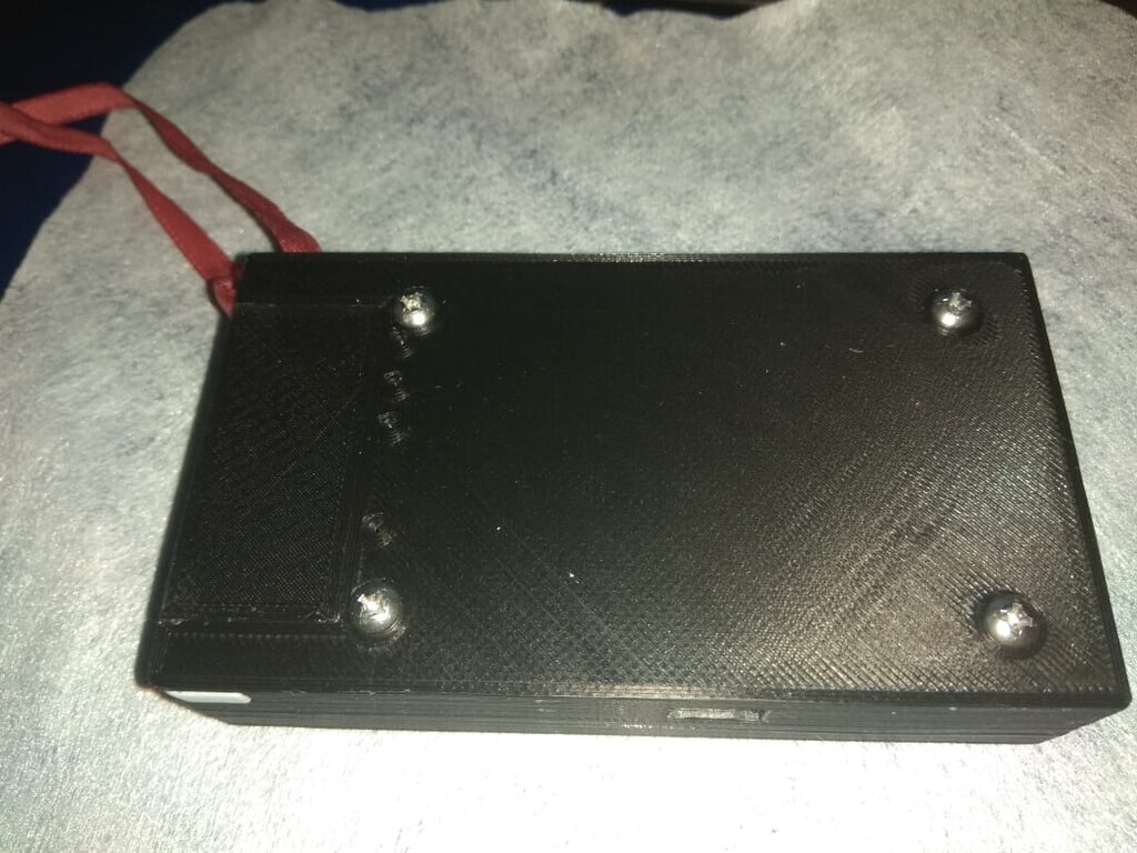
1. The 4 screw holes in the bottom part, fitting the top part,
have an offset of about 1 mm in Y direction.
The 4 holes should be moved about 1 mm in direction USB plug.
But then also the bottom part should be extended appropriate.
The 4 holes in the top part conform with my LCD PCB holes.
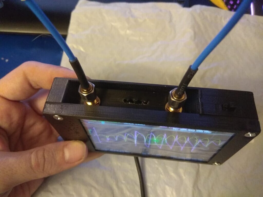
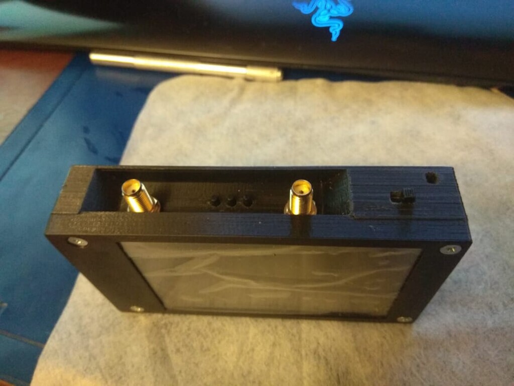
2. Long hole for the 3 switches, should be elongated at the right side, about 1 mm.
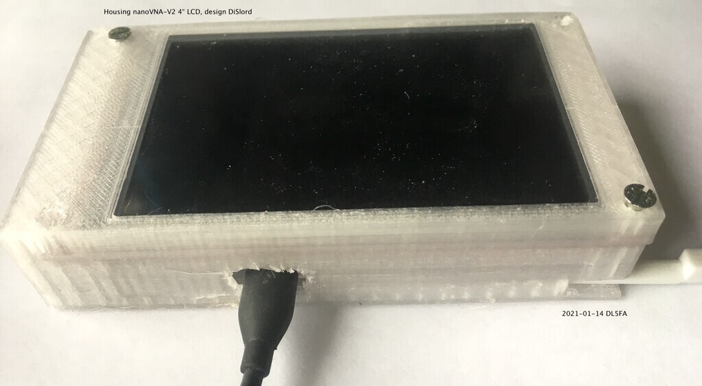
3. Hole for USB plug, should be increased to 12 x 8 mm for bigger plugs.
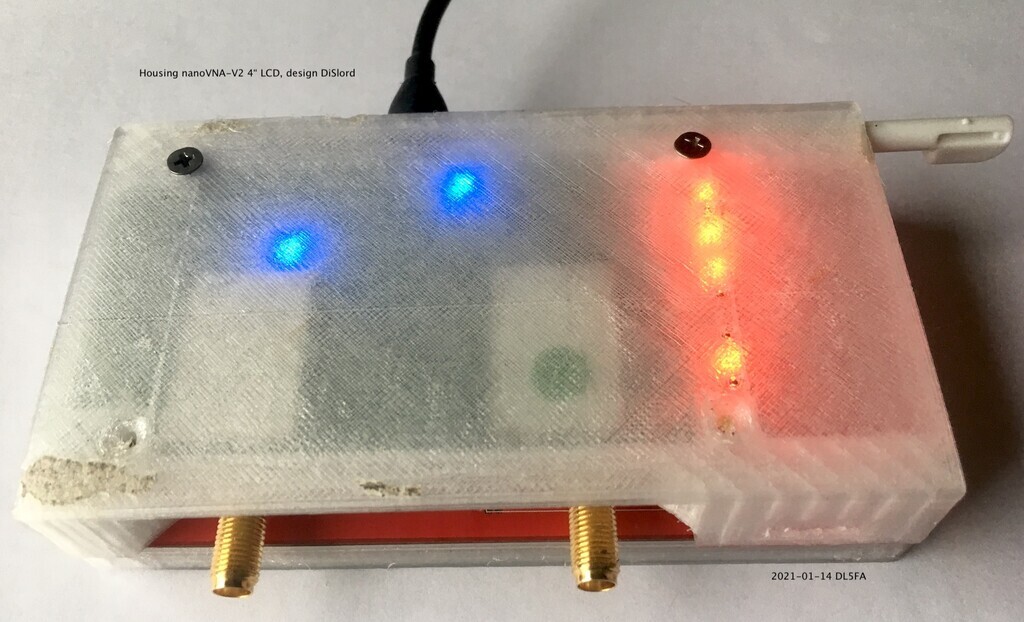
4. The wall thickness at the 4 switches is very thin with 1 mm.
A thickness of 1.5 mm would be better.
At my old housing this wall thickness is 2 mm, and you can still operate
the 3 switches, but with your finger nail ;-)
5. I have a LCD with SD-card interface. That collides with SMA port 1 of 2.
If I use just 2 diagonal screws for the top part to mount, it is OK.
6. If the 9 cm long pen for the touch screen should fit into the housing,
the PCB mounting level should be lifted up by about 2 mm.
See the attached photos.
73, Rudi DL5FA
Nice design if someone wants to replicate it:
https://www.rtl-sdr.com/nanovna-v2-enclosure-and-carry-case-now-available-on-our-store-with-release-discount/
On Thu, 14 Jan 2021 at 16:44, <reuterr@web.de> wrote:
On Thu, Jan 14, 2021 at 07:44 AM, <reuterr@web.de> wrote:
>
> 1. The 4 screw holes in the bottom part, fitting the top part,
> have an offset of about 1 mm in Y direction.
> The 4 holes should be moved about 1 mm in direction USB plug.
> But then also the bottom part should be extended appropriate.
> The 4 holes in the top part conform with my LCD PCB holes.
>
Use holes near buttons for connect V2 pcb at bottom part (see my foto), i made little mistake on measure so 2 holes at bottom need move down on 1mm (i made some fixes later, need check more features for second revision) this should fix top and bottom placement.
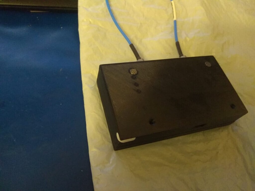
I add hole at corner for add hand lace.
Use free space in for store calibration kit.
Fix some hole positions
PS i use PETG for case, and it very strong, so 1mm thickness can be used vs it (but i try use different connection for top and bottom)
PSS this my first 3D model, i learn how 3D printing last week, so sorry fir errors.
PSS i can provide stp files for fix
On Thu, Jan 14, 2021 at 07:48 PM, DiSlord wrote:
>
> PSS this my first 3D model, i learn how 3D printing last week, so sorry fir
> errors.
>
Hello DiSlord,
I would be happy to have such a steep learning curve as you have, congratulations!
At the moment I am using transparent PLA. But I have ordered transparent PETG.
I am interested in the .stp file. You can send it to reuterr@web.de if you like.
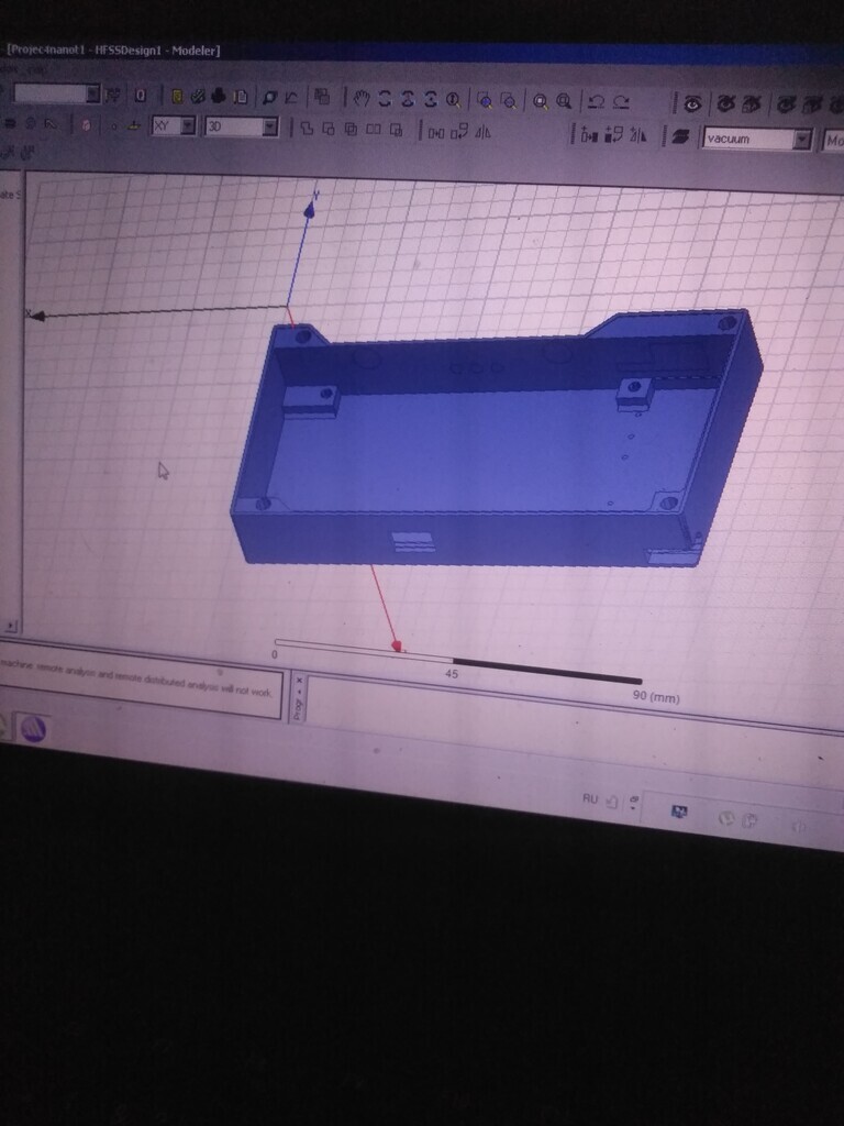
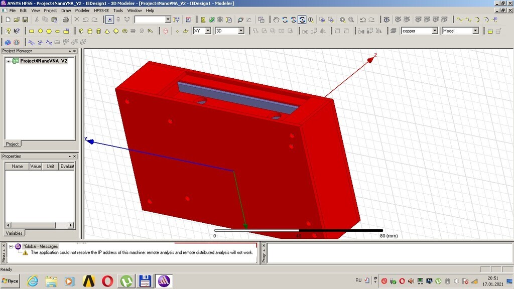
What 3D CAD program you are using?
73, Rudi DL5FA
i from Russia and use free for learning version Компас 3D (Compas 3D)
I attach files here, possibly others can provide some features for it
Does anyone know of a US based source for the 4" Display for the V2? I
bought what I thought were the correct ones from China but did not realize
that they did not have the touch screen or the IC to support it.
Thanks!
Sam
W3OHM
Sam Reaves
ARS W3OHM
Owner and Moderator of:
LeCroy Owners Group on Groups.io (Current and Future Group)
On Thu, Jan 14, 2021 at 5:57 PM DiSlord <dislordlive@gmail.com> wrote:
Hello Sam,
I had the same problem, that I got a LCD without touch.
Then I ordered from aliexpress.com, vendor Ecyberspaces:
maithoga 4.0 inch 14PIN RGB 65K SPI HD TFT LCD Screen with Adapter Board (Touch/ No Touch) ST7796S Drive IC 480*320
You have to select Color: Board with touch.
That is then just plug and play, together with the 4 inch firmware.
73, Rudi DL5FA
Hello DiSlord,
Thank you very much for the .stp files.
I can import it in program Freecad version 19, and export it as .stl file for sclicing in Cura.
https://www.freecadweb.org/downloads.php
73, Rudi DL5FA
On Fri, Jan 15, 2021 at 06:22 AM, <reuterr@web.de> wrote:
>
> Thank you very much for the .stp files.
> I can import it in program Freecad version 19, and export it as .stl file for
> sclicing in Cura.
>
Hello DiSlord,
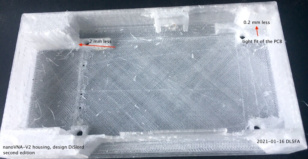
I have now printed the bottom part, second edition.
Unfortunately the addition in the upper left corner was too much (2 mm), so the PCB will not fit in place.
Also in the upper right corner the PCB fit is very tight, so 0.2 mm more space would be good.
See the picture in the appendix.
72, Rudi DL5FA
Add small fixes:
- increase wall size to 1.5mm
- add 1mm groove between top and bottom (this allow wall more hard)
- add USB cover inside
- add hole at corner for add hand lace
- fix some holes
- add box for calibration kit
PS strange, i use PLA and 0.2mm wall tinkness on my Ender 3, and get very good print quality (for example top groove have width only 0.6 mm, but perfect feet see fotos).
That looks great. Could you post the STL files?
On Sun, Jan 17, 2021, 3:17 PM DiSlord <dislordlive@gmail.com> wrote:
On Thu, Jan 14, 2021 at 11:30 PM, <reuterr@web.de> wrote:
>
> maithoga 4.0 inch 14PIN RGB 65K SPI HD TFT LCD Screen with Adapter Board
> (Touch/ No Touch) ST7796S Drive IC 480*320
>
Thanks Rudi!
Sam
W3OHM
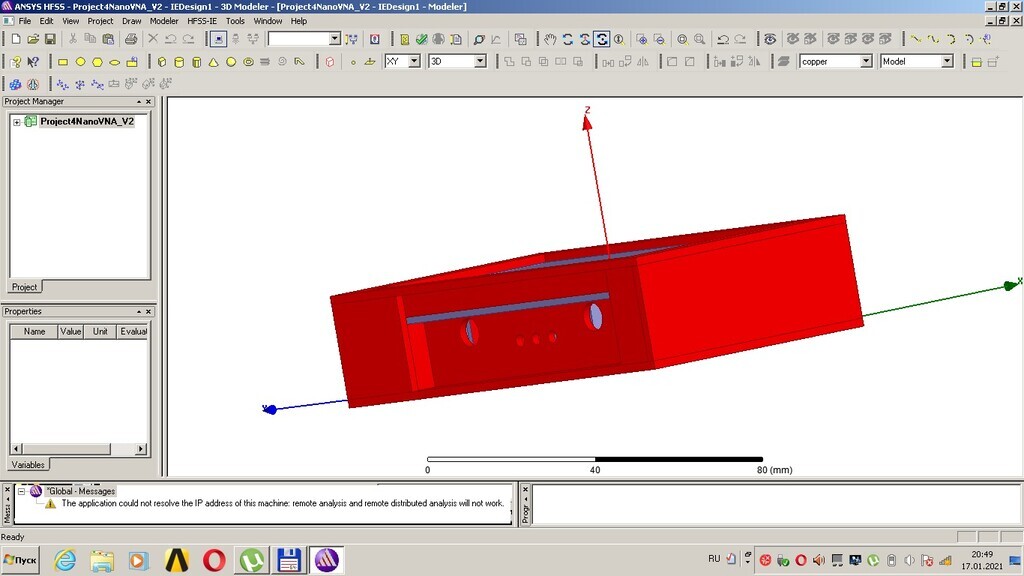
HFSS
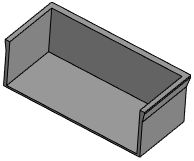
Here is last stl and stp files
Used 4 items:
- Top case
- Bottom case
- Box inside bottom (storage box)
- Cover for storage box at bottom
I public it on thingiverse
https://www.thingiverse.com/thing:4727705
To reply to this topic, join https://groups.io/g/NanoVNAV2