Beware of cheap underperforming clones

As of 2023 there are many badly performing clones on the market. V2/3GHz NanoVNA uses parts like ADF4350 and AD8342 which are costly and clones have been cutting costs by using salvaged or reject parts.

See official store and look for V2 Plus4/V2 Plus4 Pro versions only to avoid getting a bad clone. We have stopped selling V2.2 versions since October 2020, so all V2 hardware that are not Plus or Plus4 are not made by us and we can not guarantee performance.

NanoVNA V2 Forum

Note: this page is a mirror of https://groups.io/g/NanoVNAV2.
Click here to join and see most recent posts.

Receiver port impedance


Tom W8JI 2025/03/20 12:43

There were some comments about the VNA receiver port impedance not being
matched.

What particular NANO VNA has a significant port impedance issue and how
bad is it?

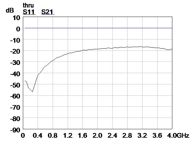
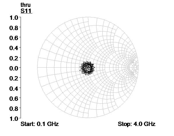
My Keysight ENA says both of the VNAs I have look pretty close to 50 j0
up to 1.5 GHz. They are only like 1.2:1 or so maximum below 1.5 GHz, and
across HF to maybe 250 MHz almost perfect.

I didn't want to go beyond that because of the cable and connectors I
was using.

What is the impedance of the bad port units? Which units have that
issue? Aren't they all copies of each other?

73 Tom

--
This email has been checked for viruses by AVG antivirus software.
www.avg.com

Roger Need 2025/03/20 22:24

Tom,

NanoVNA-H and NanoVNA-H4 have poor Port 1 and Port2 impedance characteristics.

Don’t know about other products.

Roger

Jim Lux 2025/03/21 14:08

The original NanoVNA (with the 2.x” screen) has a 17 dB (or something like that, I can’t remember the exact value) resistive pad on CH1 (port 2) before the input to the mixer. It’s pretty close to the actual connector, so it’s probably pretty good up to 900 MHz (the top freq for the original design) assuming the resistors are 1%.

The CH0 is a resistive bridge made of 100 and 50 ohm resistors, so all told probably within a few percent, considering what the bridge is connected to and fed from.

It kind of depends on what “significant impedance issue” means in this context. And whether it “calibrates out”. The source impedance (CH0) would probably calibrate out in the SOL cal.
The CH1 impedance, not as much - when you do the thru cal, you’re sort of rolling the CH1 gain and mismatch into one measurement. Yes, you are measuring the power reflected back with the CH0 bridge (which is calibrated), so that *should* essentially measure the difference from 50 ohms, but it is intertwined with the other cal measurements (for instance, Does the SOL CH0 cal actually determine the source impedance of the port?)

Some of the other newer models have switches at the input which may or may not affect the match on the ports - I’ve not looked the design in as much detail.

John Gord 2025/03/21 17:43

Roger,
I checked my H4, HW version 4.3_MS:
Port 2 is better than 25dB RL to 1GHz.
Port 1 is better than 20dB RL to 1GHz,
I wouldn't call that poor.
(The corresponding uncorrected RL limits for the 8753D are 18dB and 16 dB to 1.3GHz.)
--John Gord

On Fri, Mar 21, 2025 at 09:59 AM, Roger Need wrote:

biastee 2025/03/21 22:08

Tom,
I have a HCXQS-supplied V2+. The S11 traces below are actually measuring Port 2 because the ports are connected with a coax.
• Port2 RL better than -20 dB (SWR <1.2) below 1.6 GHz
• Over 1.6~4.0 GHz, port2 RL < -15 dB (SWR <1.5)
I didn't measure the port 1 match bcos the V2+ is incapable of doing that.
Hence, when I want to measure the S11 of a DUT with poor reverse isolation, e.g. biastee / cable, I will connect a 10 dB attenuator to port 2.
73, Leong, 9M2LCL, ex-9W2LC

Roger Need 2025/03/23 15:12

On Fri, Mar 21, 2025 at 08:00 PM, John Gord wrote:

>
> I checked my H4, HW version 4.3_MS:
> Port 2 is better than 25dB RL to 1GHz.
> Port 1 is better than 20dB RL to 1GHz,
> I wouldn't call that poor.
>
>

Return Loss is only part of the story.  It depends on what you are doing.  When making impedance measurements using the "S21 series" method the Port 2 (CH1 on some NanoVNA's)  needs to be very close  to 50 ohms in order to get accurate results.

Here are some plots made on a NanoVNA-H Port2 (CH1)which is the older 2.8" version. RL is worse case -17 dB but look how far off 50+j0 the results are as the frequency increases.

These plots were made on an older NanoVNA-H4 version 4.2 SI.  Much better RL but still not close to 50+j0 as frequency increases.

One trick that can be used is to add an attenuator to Port 2 and then "cal it out" during calibration.  Note the improvement.

To reply to this topic, join https://groups.io/g/NanoVNAV2

View this thread on groups.io