
This may or may not be of interest (first post here too).
Intro - just picked up a NanoVNA V2 which looks like the discontinued "2.8 V2 with metal case" version going by the official website.
It came from Ebay so am not sure of whether it is a clone etc. but seems to function fine and I updated to the recommended firmware (20201013).
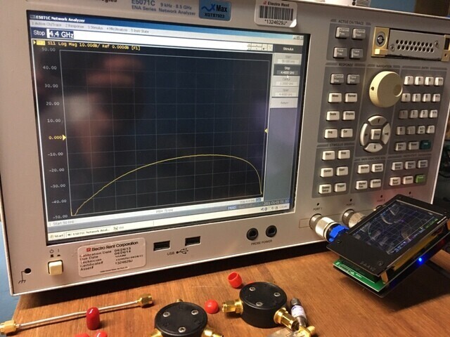
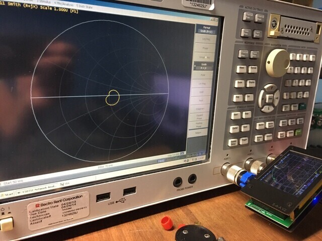
Whilst evaluating it the first few days, I calibrated port1 to the end of a supplied SMA cable using the supplied standards and had a look at the full range return loss of the second port - it was only about 10dB or even slightly worse at 3GHz, so not quite meeting spec for some reason.
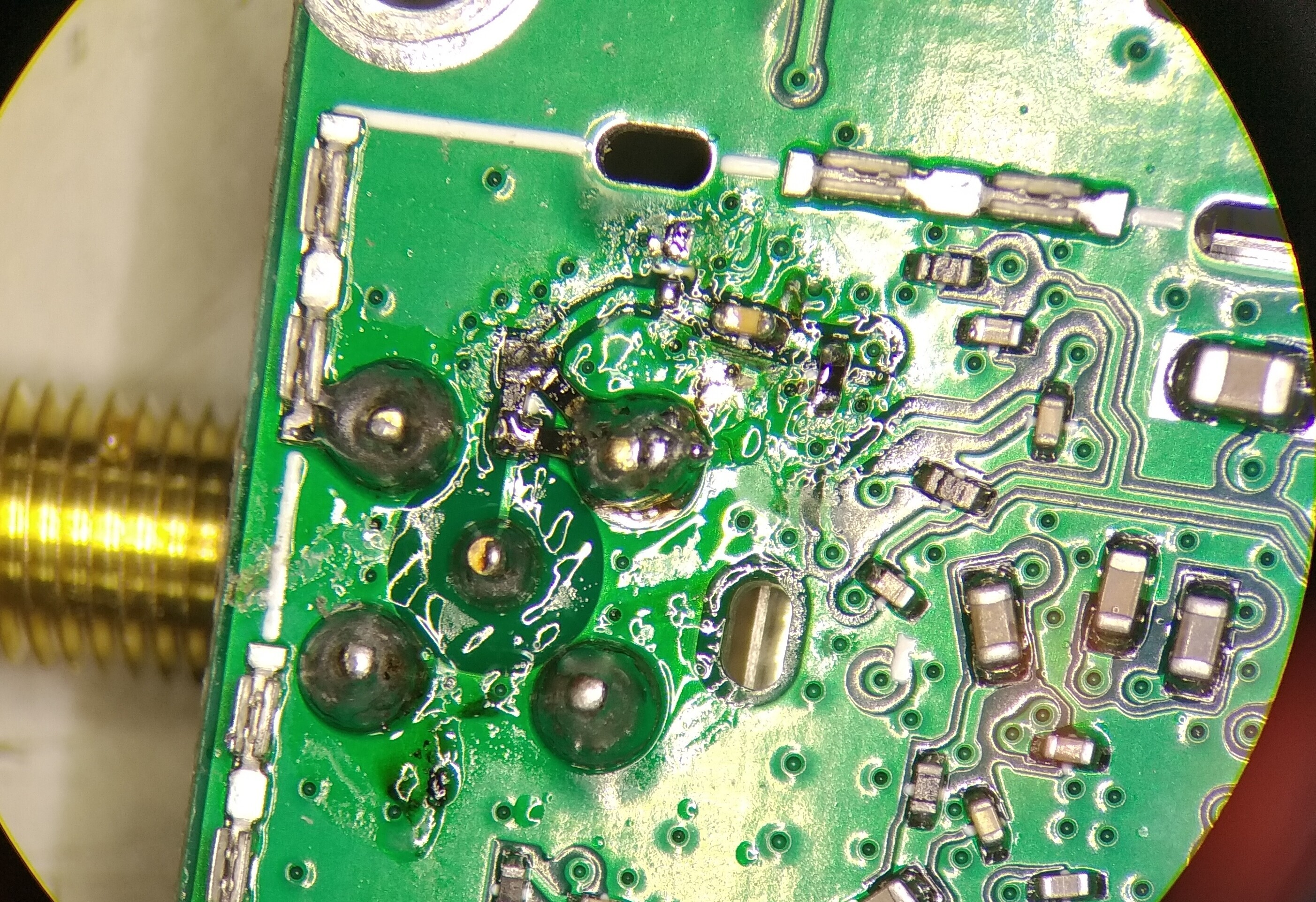
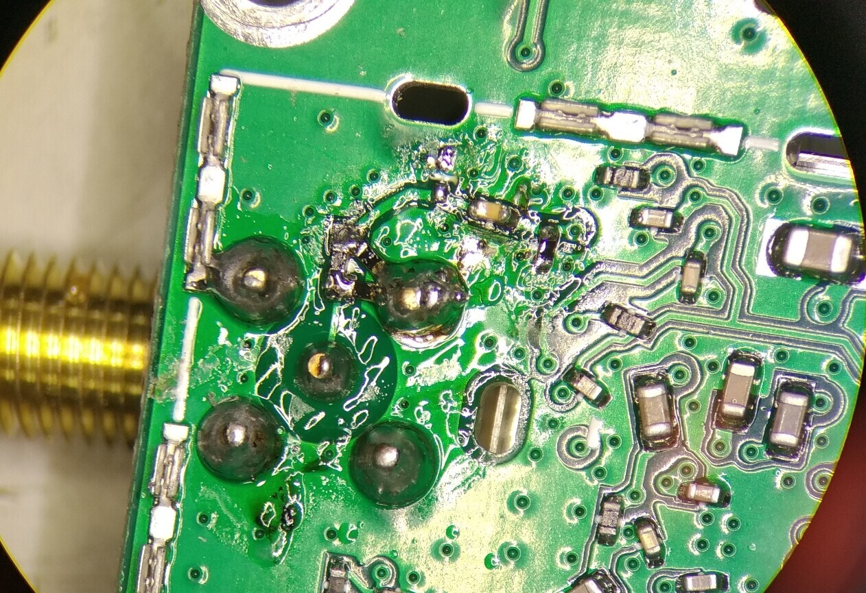
As the unit has a wonderful low cost, I have no qualms about tinkering with it! Looking at the schematic I saw at least one thing to investigate - the input series capacitor C8. The value of this capacitor in the schematic at 10uF is heavily skewed to low frequency operation and at any RF frequency over several MHz will be well beyond its self-resonance frequency and will effectively be an inductor thereby potentially degrading return loss - decided to place a low value capacitor in parallel with a larger value. Also I decided to move the pi-attenuator (3 resistors) closer to the SMA connector pin as this then somewhat isolates the external port from the capacitor. So in the end I swapped the location of the pi-attenuator with the capacitance. The resistors were re-used but the capacitor changed to a 2.2uF 0402 in parallel with a 100pF 0402.
*So Summary of Changes:*
C8 changed to the series resistor 120ohms
75ohm 0402 Resistors moved from R10 & R11 to either side of the 120ohm resistor (location C8), soldered to one of the SMA connector ground pads.
R9 then became a 2.2uF 0402 capacitor with an 0402 100pF cap piggy backed on top.
As I'm not sure of whether or not the switch input required a DC path at the input I also put a 511ohm 0402 resistor to ground at location R11
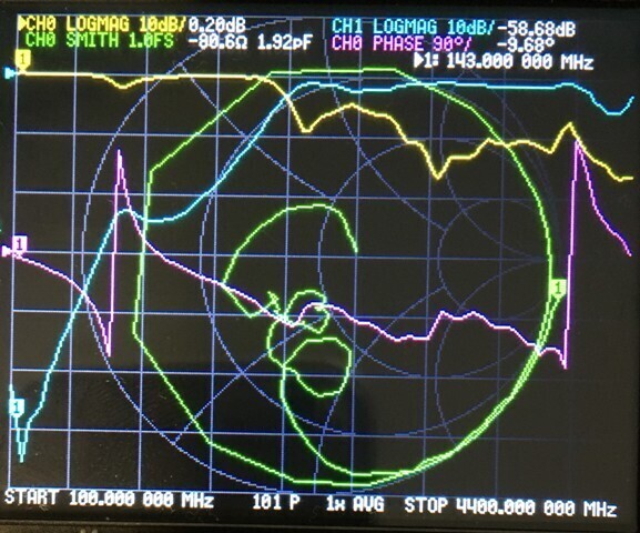
*Result* - port 2 return loss now >14dB at <=3GHz (though when I get access to a big VNA at work I'll try to confirm rather than self test by a cal using the supplied reference standards)
Other comments - I measured the resistor values (correct) and also checked the switch components were the correct type - ok. I also put a 100pF 0402 cap piggy backed upon C1 and C306 while I was in there (these are also 10uF capacitors in the RF paths). Also note I didn't do an exhaustive search of parallel capacitor values to use (lack of time so far) - it could be that 22pF, for sake of example, in parallel with the uF cap may give better results still since this gives even lower impedance at GHz frequencies than 100pF..
Apologies if this has been covered elsewhere already!