Francesco 2021/10/31 05:16
Hello Jim, thank you for your generous offer to drive me on the ragth
direction.
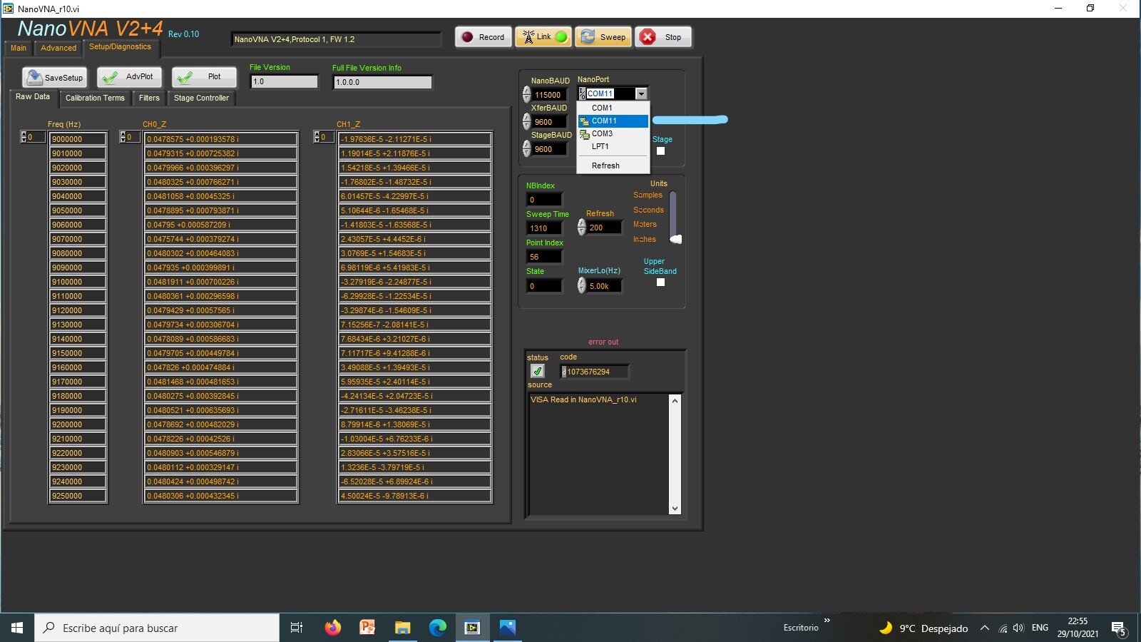
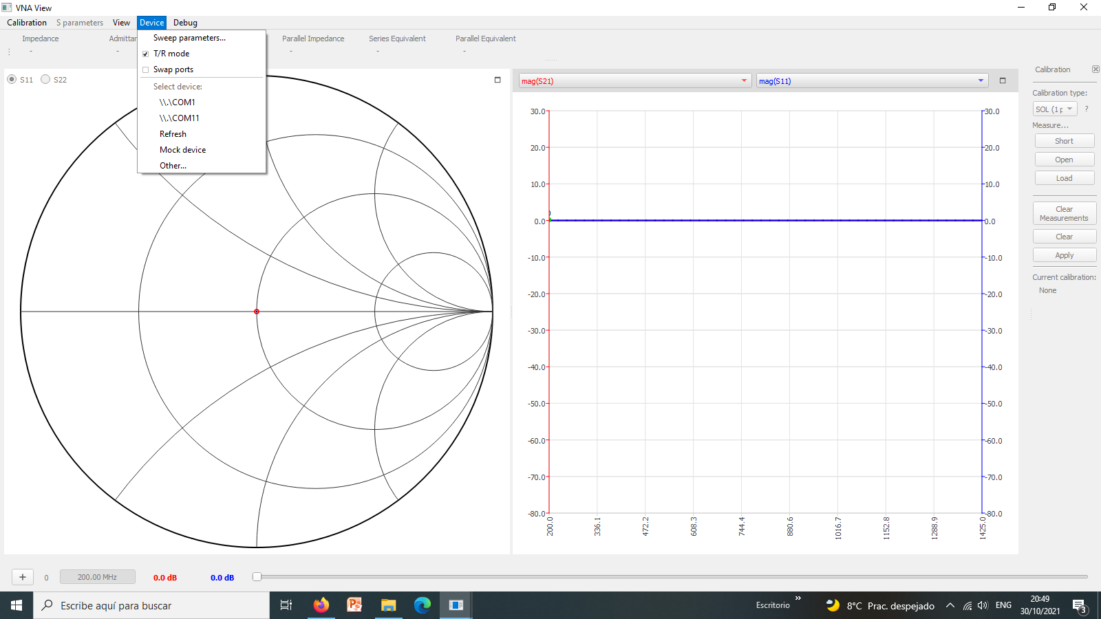
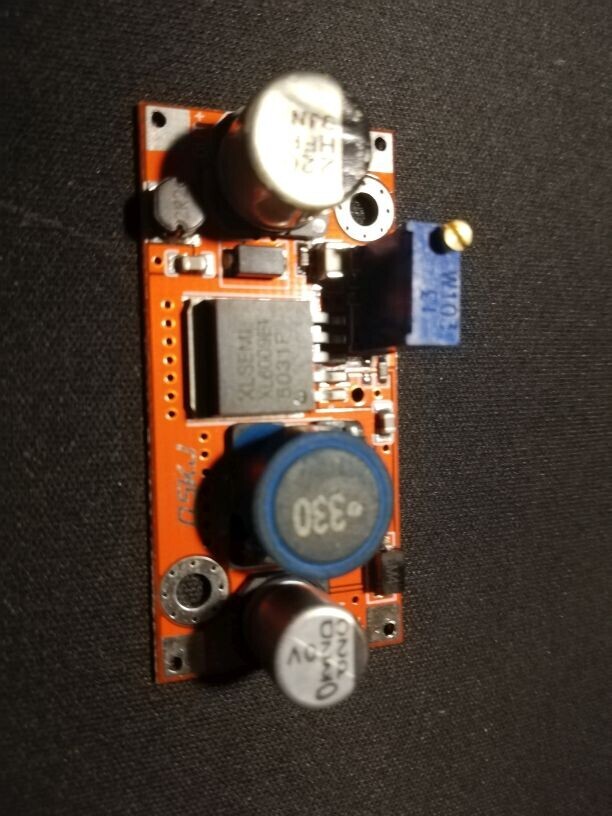
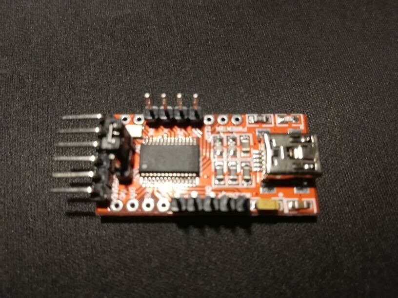
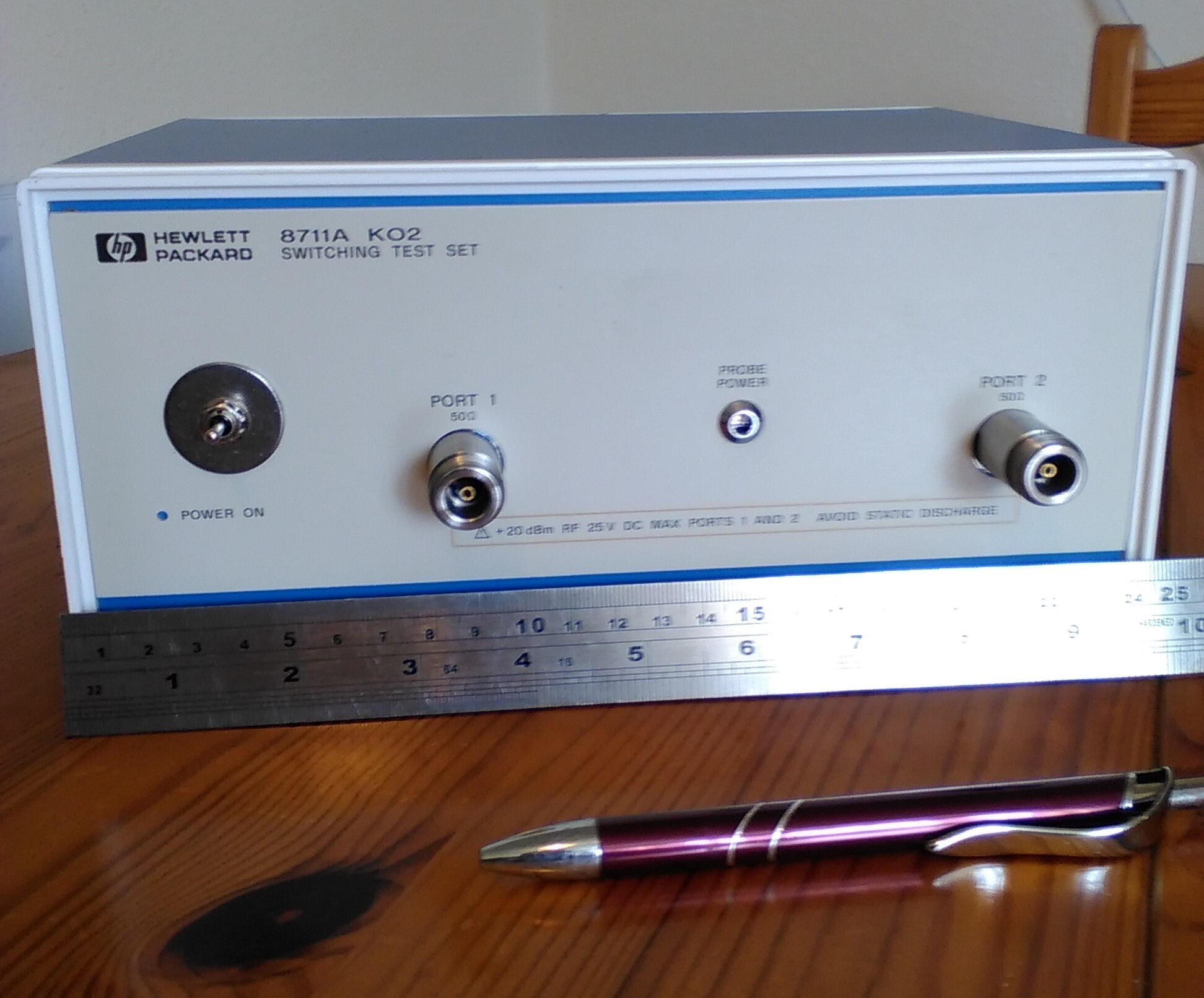
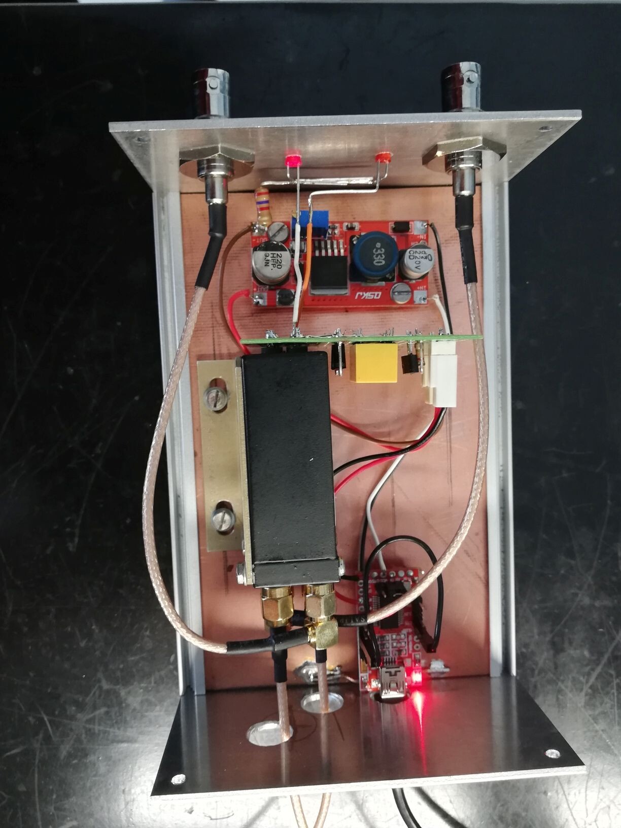
This is the board on my possession, stand alone with is small software work
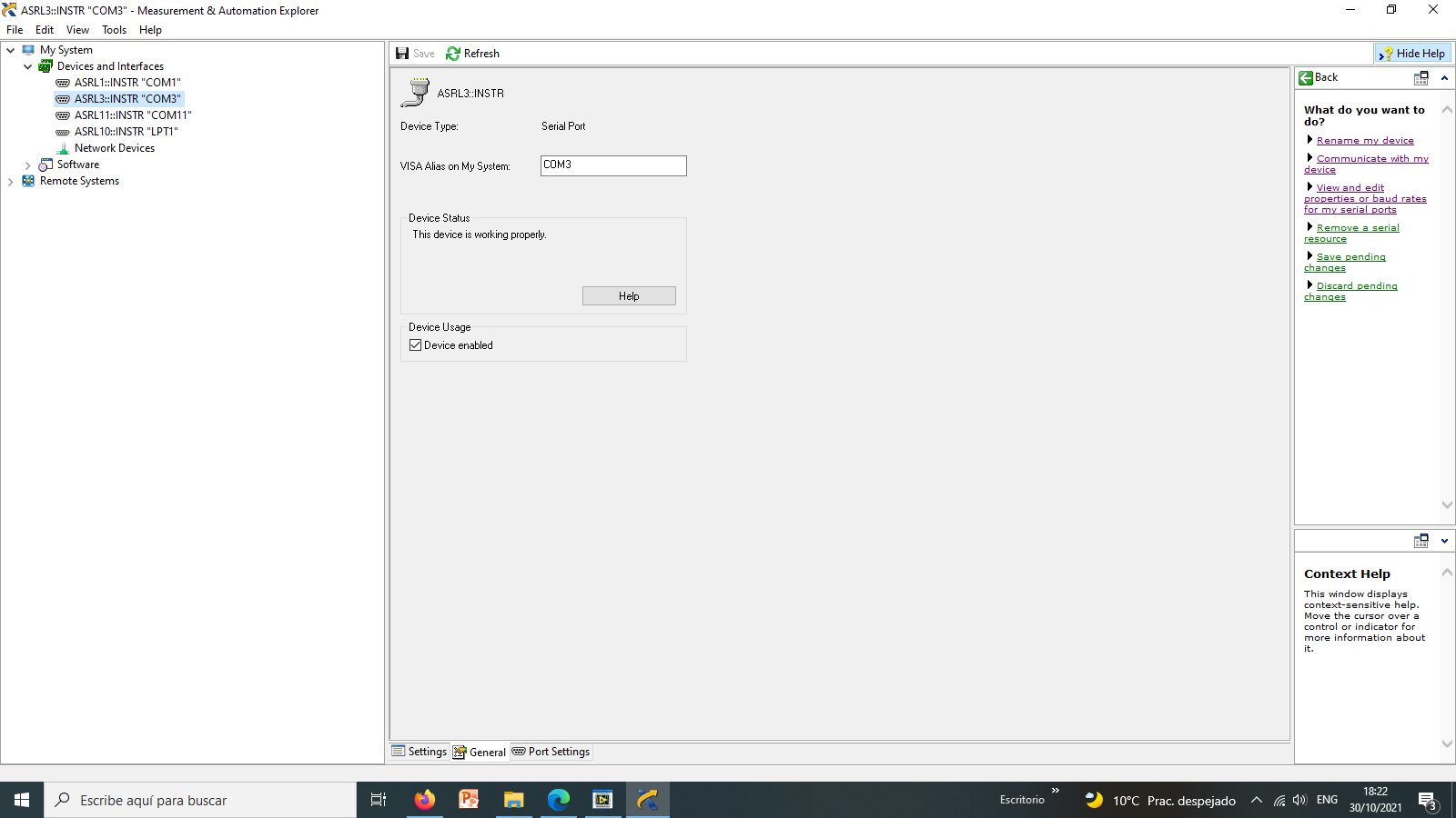
perfect, the pc reconize the driver, the the NanoVNA software reconoice the
usb board (tell me there is one error , LabWiu see de board is ok.
I read on the JS software manual:
**The software really doesn 't care what type of transfer relay is attached.
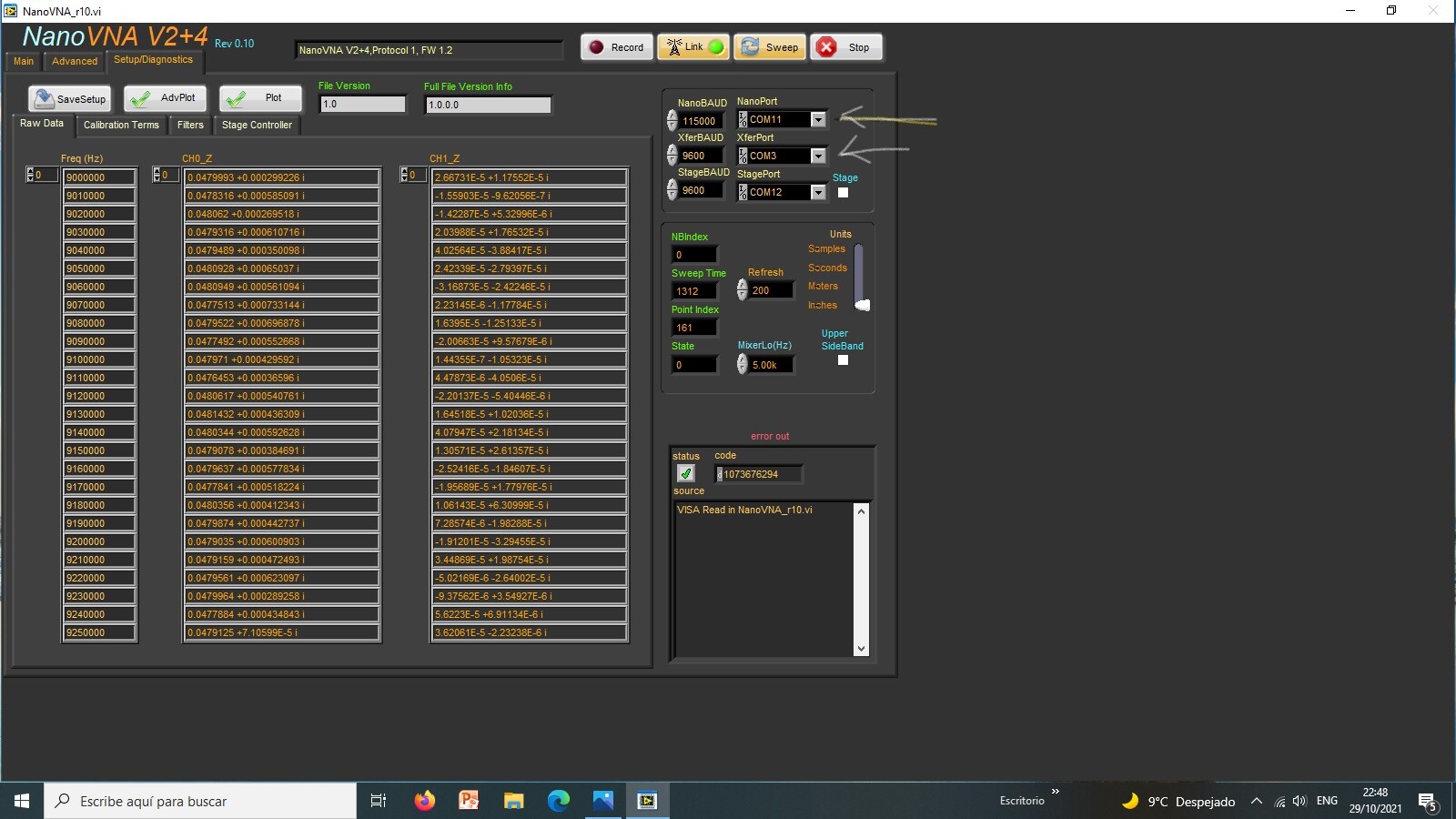
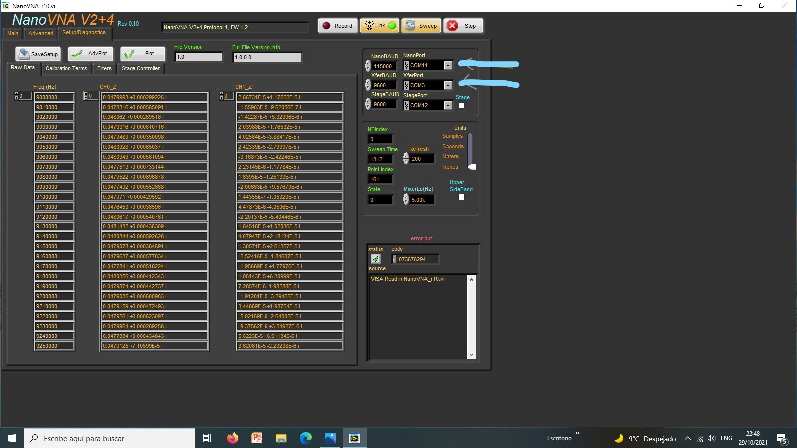
It uses a common USB - TTL adapter from FTDI. The RTS signal is used to select
the state of the relay and the CTS is used to monitor it's status. The
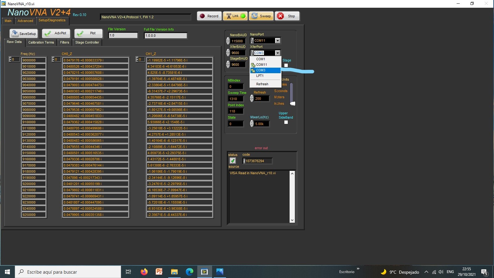
communications port is selected in the Setup/Diagnostics page using the
XferPort. Again, the BAUD rate has no effect. The selected port is saved as
part of the defaults. Shown is the FTDI cable attached to the Transco
controller.**
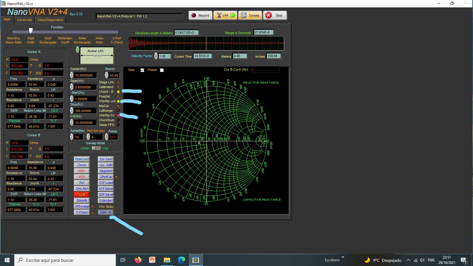
**19.1 Manually Controlling the Transfer Relay With the correct communications
port selected, the next time Link is selected, the software will check for the
presence of the port. There is no other check beyond it finding a valid port
number. If found the XferRly Lnk indicator (found on the main page), will
become active. You can manually change the state of the relay by selecting the
CH0-A switch on the front panel. Once selected, the Chan0-B indicator will
become active. If the relay does not change states, the XferRly Err indicator
will become active.**
Is possible from the NanoVNA software and the board some signal not floing?
**The RTS signal is used to select the state of the relay and the CTS is used
to monitor it 's status.**
**If I need to buy other relay bord is not problem.**
**Sorry Jim I 'm confused.**
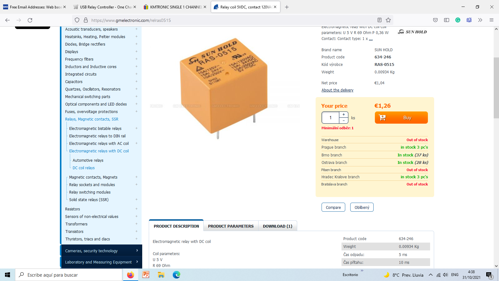
**A general purpose USB Relay controller for connection to a PC 's USB port
using VCP (Virtual COM port). Control devices using your PC. USB Relay
controller allows a PC to control a single external device using simple RS232
commands. Relay is fully powered from the USB bus. Free test software.**
** ****Features:**
• Fully assembled and tested.
• Fully powered from USB
• For 12V/24V DC 15A or 120V/220V AC at 10A max.
• Can be used with LabVIEW, ProfiLab, DAQFactory, TestPoint, DASYLab, VEE
****
**** ******Model:**
U1CR
**** ******Complete
including:**
\- One USB One relay controller
** ****Dimensions** **
**(PCB board)** :**
90 mm / 35 mm
**** ** Drivers:**
<http://www.ftdichip.com/Drivers/VCP.htm>
** ****Drivers are
available to work with the following operating systems:**
All Windows Systems, Linux, Mac OS X, Mac OS 9, Mac OS 8, Windows CE.NET
(Version 4.2 and greater)
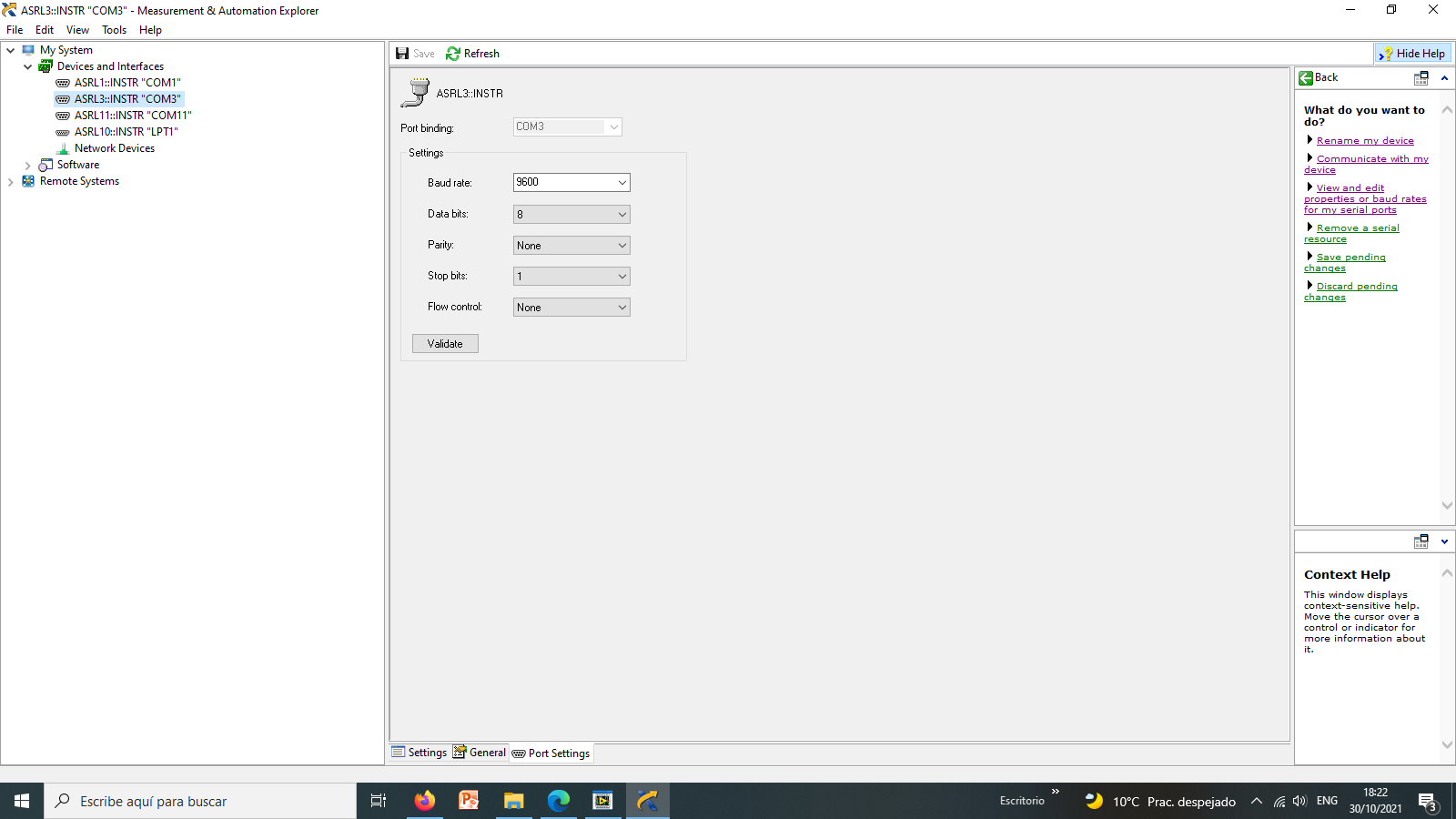
** ****Communication
Parameters:**
8 Data, 1 Stop, No Parity
Baud rate : 9600
** ****Commands:**
OFF command: FF 01 00 (HEX) or 255 1 0 (DEC)
ON command: FF 01 01 (HEX) or 255 1 1 (DEC)
** ****Software:**
Download - [KMTronic_USB_Timer.zip](http://sigma-
shop.com/software/usb_relay/KMTronic_USB_Timer.zip)
****
** More information:**
[info.KMtronic.com/USB-One-Channel-Relay-
PCB.html](http://info.kmtronic.com/usb-one-channel-relay-pcb.html)
** Software
examples:**
[info.KMtronic.com/USB-RS232-RS485-Relays.html](http://info.kmtronic.com/usb-
rs232-rs485-relays.html)
**Sent:** Sunday, October 31, 2021 at 1:21 AM
**From:** "Jim Lux" <jim@luxfamily.com>
**To:** NanoVNAV2@groups.io
**Subject:** Re: [nanovnav2] Please some help to integrate trasfere relay
On 10/30/21 6:12 PM, Jim Lux wrote:
> On 10/30/21 5:56 PM, John Galbreath via groups.io wrote:
>> please show link to specification of this board.
>> looks like you are headed in right direction.
>> _._,_
>
>
> I've been fooling with USB relay boards recently, and there's
> *multiple* FTDI chips that get used. Sometimes they're using one of
> the older ones, and repurposing lines like RTS. The newer FTDI chips
> can be used as a sort of parallel port interface. A lot depends on
> the device driver on the PC to set them up (and be aware, the random
> vendor on Amazon may or may not be distributing drivers or sample code
> that matches *their* particular implementation).
Found some notes. the FT-245R is different than the FT-232 series. The
FT-245R requires a sequence to put it in "bit bang mode"
There are *other* USB relay boards that take a byte sequence to command
the relay on off. For instance, the SainSmart 8CH relay uses 0xff,
channel, 0x1 to turn the relay #channel on, and 0xff, channel, 0x0 to
turn it off. You can send 0xff, 0x8+channel and get the relay state back.
_._,_._,_
* * *
