
Hi Bob,
Jim Lux said it one way. I will say what he said a different way.
The two dipoles have mutual coupling across space. Since the two
antennas are not exactly in phase or exactly out of phase, but are
actually vastly different in phase, they will have quite different feed
point impedances. This difference in phase of fields from antenna 1
reaching antenna 2 and from the fields of antenna 2 reaching antenna 1
will shift both the reactance and the resistance quite differently at
each antenna feed point. The grossly dissimilar feed point impedance
shifts will cause the feed lines and phasing lines to not behave like we
might think.
In operation the real phase shift and current levels will not be
anywhere near equal and not have the 90 degrees lag you cut the delay
cable for.
The only way to measure the real phase shift and current levels (we
usually want a two element to have equal currents in each element, not
equal voltage or equal power) you would need to excite the antenna and
measure the vector currents in each element. The Nano VNA will not help
you do this.
Modeling the antenna array with the phasing and feed lines in the model
is by far the easiest thing to do. The NanoVNA can help characterize the
transmission lines and the antennas for use in a model or verify the
model, but the VNA cannot tell you how the antenna system is behaving.
I hope this helps..
73 Tom
On 6/12/2025 4:07 PM, Bob via groups.io wrote:
> I would like the NaNoVNA to help me steer my dual dipole array. I
> have 2 15m dipoles running E/W, so there is a S. Antenna and a N.
> Antenna. Currently I have the same length of quad shielded feed cable
> running from each antenna to a splitter box. The S. Antenna has a 1/4
> wave phasing cable along with the basic cable length with a goal of
> steering the detection to 65/70 degrees above the S. Horizon. My
> questions are:
> 1/ Can I use the NanoVNA to determine the phase angle between the two
> feeder cables? Ideally I would like to hook North up to S11 and the
> other (South) to S21 to confirm no phase difference. This would
> confirm that both feeder cables were the same length and the beam was
> 90 degrees straight up.
> 2/ I'd then like to check my phase cables to the S. Antenna to confirm
> they are 90 and 135 degrees compared to the N.
> I have some basic understanding of engineering/physics but what I
> could really use is a procedure and some guidance to interpret the
> results. Any assistance (including saying you can't do that with a
> NaNoVNA) would be appreciated.
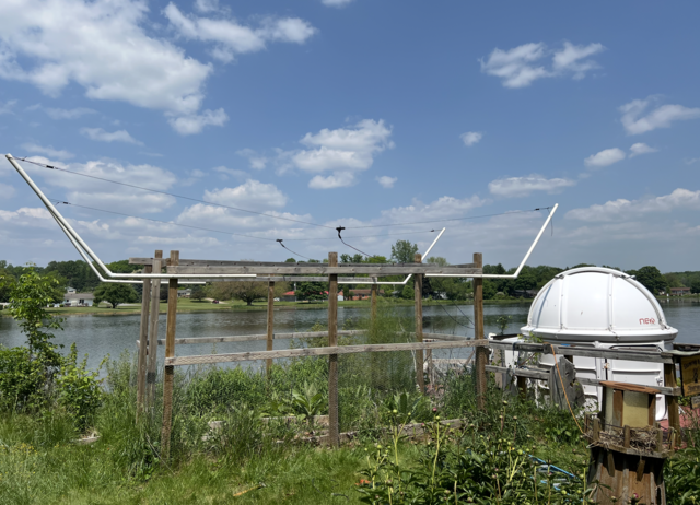
> For background, the application is a Radio Jove antenna to detect
> Solar and Jupiter Radio Bursts at 20.1 MHz. I have linked a photo of
> the set up.
> Thanks in advance,
> Bob
>
--
This email has been checked for viruses by AVG antivirus software.
www.avg.com