Beware of cheap underperforming clones

As of 2022 there are many badly performing clones on the market. V2/3GHz NanoVNA uses parts like ADF4350 and AD8342 which are costly and clones have been cutting costs by using salvaged or reject parts.

See official store and look for V2 Plus4/V2 Plus4 Pro versions only to avoid getting a bad clone. We have stopped selling V2.2 versions since October 2020, so all V2 hardware that are not Plus or Plus4 are not made by us and we can not guarantee performance.

NanoVNA V2 Forum

Note: this page is a mirror of https://groups.io/g/NanoVNAV2.
Click here to join and see most recent posts.

Measuring ferrite antennas gives odd results


Leif M 2022/09/07 00:11

I tried to measure coils which are on a ferrite rod. Results are odd, there is no constant inductance, no resonances. Is this RF voltage, because these rods are used as MW or SW antennas.
I use V2 Plus4. Frequency range is from 50kHz to 10MHz. I have two ferrite antennas, and both give similar results.

Lou W7HV 2022/09/08 12:32

Ferrite rod antennas are different.  The ferrite rod and coils need to be part of a resonant circuit to work, like a small loop antenna in essence.  And depending on the situation, its resonance may be nowhere near 50 ohm.  Best to google ferrite rod antennas and read up on them.

Roger Need 2022/09/09 08:42

On Wed, Sep 7, 2022 at 05:27 AM, Leif M wrote:

>
> I tried to measure coils which are on a ferrite rod. Results are odd,
> there is no constant inductance, no resonances.

Try these links about ferrite rod coils:
https://coil32.net/ferrite-rod-core-coil.html
https://coil32.net/files/Alan_Payne/Web-The-Inductance-of-Ferrite-Rod-Antennas-issue-3.pdf

Roger

W0LEV 2022/09/09 16:37

Just a suggestion: Measure your coil(s) without the ferrite rod. You may
have to parallel a small capacitor to bring resonance down. Then watch the
inductance and ultimately resonance as you slowly slide the rod into the
coil(s).

Dave - WØLEV

On Fri, Sep 9, 2022 at 4:31 PM Roger Need via groups.io <sailtamarack=
yahoo.ca@groups.io> wrote:

> On Wed, Sep 7, 2022 at 05:27 AM, Leif M wrote:
>
> I tried to measure coils which are on a ferrite rod. Results are odd,
> there is no constant inductance, no resonances.
>
> Try these links about ferrite rod coils:
> https://coil32.net/ferrite-rod-core-coil.html
>
> https://coil32.net/files/Alan_Payne/Web-The-Inductance-of-Ferrite-Rod-Antennas-issue-3.pdf
>
> Roger
>
>
>

--
*Dave - WØLEV*
*Just Let Darwin Work*

Hank Hamner 2022/09/09 11:46

Usually a ferrite rod antenna is just part of an antenna system and is not
necessarily at 50 ohms. Remember, maximum power is transferred when the
output impedance of the antenna matches the transmitted power. This could
be 50 ohms, 75 ohms, 600 ohms or any other impedance. This is especially
true of older RF devices.

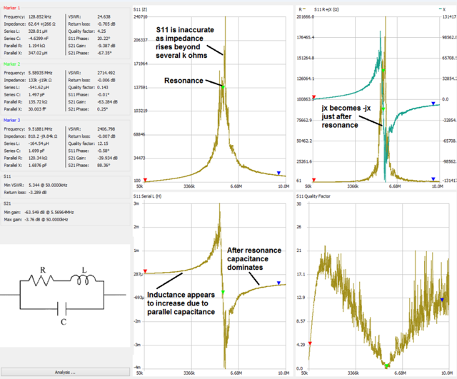
Ferrite cores (rods, toroids or other configurations) wrapped with wire are
merely inductors (aka coils). Depending upon the frequency you want to
tune to, a fixed inductor with a variable capacitor may be needed. The
higher the frequency generally the smaller the inductor in Henries and the
smaller the capacitor in Farads. Also, the higher the frequency the more
the inductive and capacitive reactances are affected by parasitics that can
cause unpredictable results.

At the AM frequencies you will find a lot of ferrite rod antennas but very
few at the higher frequencies (HF and higher). Study up on ferrite
properties and also study up on how and when to calculate and measure
circuit quality (Q) properties to your advantage. Remember, high Q's
generally mean lower bandwidth and vice versa.

A lot of experimentation is involved in the RF world because it seems like
everything is affected by and affects anything close by. Fortunately our
nanoVNAs and TinySA spectrum analyzers are great tools to help with this.
Also, don't forget about how to use the old grid dip meter coil attachment
plugged into the s1 nanoVNA port to help tune RLC circuits without loading
the circuits.

Good luck!

Hank


On Fri, Sep 9, 2022 at 9:26 AM Lou W7HV via groups.io <louandzip=
yahoo.com@groups.io> wrote:

Hank Hamner 2022/09/09 11:56

Inductance varies with frequency with the formula of an ideal inductor's
reactance:

Xl = inductive reactance in Henries
f = frequency
L = inductance in Henries

Xl = 2 * pi * f * L

An *Ideal* 1 uH inductor with very short leads at 1 MHz should measure 6.28
Inductive Reactance in Ohms and 62.83 Ohms at 10 MHz.

Resonanct frequencies are based on a lot of factors including parasitics in
the component. At some frequency every inductor and capacitor will self
resonate.

On Fri, Sep 9, 2022 at 11:31 AM Roger Need via groups.io <sailtamarack=
yahoo.ca@groups.io> wrote:

Jim Lux 2022/09/09 11:43

On 9/9/22 9:46 AM, Hank Hamner wrote:
> Usually a ferrite rod antenna is just part of an antenna system and is
> not necessarily at 50 ohms.  Remember, maximum power is transferred when
> the output impedance of the antenna matches the transmitted power.  This
> could be 50 ohms, 75 ohms, 600 ohms or any other impedance.  This is
> especially true of older RF devices.


Ferrite rods are usually used for receiving. In lots of applications,
one doesn't care about maximum power transfer in a Thevenin sense (i.e.
we don't try to match the output impedance of a DC power supply to the
load impedance).


In receiving applications for low frequencies (where background noise is
high) one might use a high Z low noise preamplifier from a fairly
egregiously mismatched antenna (think a 2 meter whip at 1000 kHz AM ).
The antenna Z is probably -500k j and the receiver Z is a few hundred k
resistive. So the receiver sees about half the voltage you'd get from an
open circuit load, and that's plenty to demodulate.

There's no real attempt to have high efficiency in a power transfer
sense - just "enough voltage". Ferrite loopsticks are a magnetic
antenna - same general idea as a whip, except for H field instead of E
field. So you want a LOT of turns, you want the flux to be "inside the
turns) (which is where a core helps), and you want low resistance
(because you don't want to lose voltage in the drop across that
resistance, into your load)


What you want in a transmitting antenna is "maximum radiated power",
which may or may not be with a Thevenin match (many transmitters are not
constant power, constant impedance sources). But that's whole other issue.

singhonlo 2022/09/10 03:28

Your question is unclear. Are you trying to measure LC parallel resonance or self-resonance of a ferrite cored inductor on its own? Most radio MW ferrite rods start to become lossy above 2 MHz. You cannot use NanoVNA to characterise any LC, The parallel LC resonance tank is a high impedance circuit. However you can use NanoVNA to measure low-impedance series resonance with great care. The accuracy of the V2 plus 4 starts to degrade rapidly under 10MHz. It is not a trivial measurement, you have to know what you are doing.

Reinier Gerritsen 2022/09/10 15:13

The problem may be the V2Plus4. It is not suited for high-Q networks
like crystals ferrite rods. The input is switched during measurements to
compensate for drift I think. Only in this particular case, you are
better off with an old NanoVNA. Or one of the newer models like the
V2Plus4Pro or the VNA6000, but these are more expensive.

Reinier


Op 7-9-2022 om 09:11 schreef Leif M:

Roger Need 2022/09/13 17:06

On Sat, Sep 10, 2022 at 07:56 PM, singhonlo wrote:

>
> You cannot use NanoVNA to characterise any LC, The parallel LC resonance
> tank is a high impedance circuit.

Not sure what you mean by your statement.  Here is a S11 shunt measurement done on an LC circuit below 10 MHz using a NanoVNA. You can clearly see the self resonant frequency and measure the inductor value at low frequency.  You can't measure the resistance at resonance using S11 shunt method but you can with S21 series method.

resonance and

Roger

Hank Hamner 2022/09/14 06:12

I agree with Roger. I measure inductors, capacitors and resonance all the
time with my nanoVNA-H4. I use my H4 because the native firmware has so
many features compared to my other nanoVNA's and I don't need GigaHertz
range.

On Tue, Sep 13, 2022 at 10:41 PM Roger Need via groups.io <sailtamarack=
yahoo.ca@groups.io> wrote:

W0LEV 2022/09/14 15:43

You can use the NANOs to measure resonance, if you treat the measurement as
though you are using a GDO (Grid Dip Oscillator). Terminate the source
port (S11) with a small value inductance (for the frequency of
measurement). As with a GDO, then hold the small-value inductor close to
the circuit under investigation. You should then detect a dip, just as
with a GDO, at the resonant frequency. Note this also works for measuring
antenna traps.

Dave - WØLEV

On Wed, Sep 14, 2022 at 3:41 AM Roger Need via groups.io <sailtamarack=
yahoo.ca@groups.io> wrote:

> On Sat, Sep 10, 2022 at 07:56 PM, singhonlo wrote:
>
> You cannot use NanoVNA to characterise any LC, The parallel LC resonance
> tank is a high impedance circuit.
>
> Not sure what you mean by your statement. Here is a S11 shunt measurement
> done on an LC circuit below 10 MHz using a NanoVNA. You can clearly see the
> self resonant frequency and measure the inductor value at low frequency.
> You can't measure the resistance at resonance using S11 shunt method but
> you can with S21 series method.
>
>
> resonance and
>
> Roger
>
>
>

--
*Dave - WØLEV*
*Just Let Darwin Work*

Hank Hamner 2022/09/14 13:12

I just use S21 and my H4 gives me resonant freq ( parallel or serial) and
resistance and reactance of the DUT. I think using S11 may be more
complicated but that's just a personal opinion.


On Wed, Sep 14, 2022 at 12:31 PM W0LEV <davearea51a@gmail.com> wrote:

singhonlo 2022/09/15 02:13

You can see the peaks and dips in S12 and S11. It does not guarantee they are accurate or even remotely correct.
The nanoVNA has 50 ohms input and output impedance. The parallel LC resonator has high Z. The moment you attached the NanoVNA to a parallel :LC, it will load it down and damp the Q, potentially shifting the resonance frequency. Try this with a 10.7MHz IF transformer, see what you will get.

To measure the parallel LC properly, you would need to "lightly couple" both the input and out of the lank inductively or capacitively.

This dip meter can be fiddly and not always work. The accuracy of the measurement is affected by the level of inductive coupling. If it is too close to the  LC, the dip meter becomes part of the circuit, shifting the resonance point. You can use the V2 plus 4 with a coil detector probe of one turn, the high dynamic 90db-100db range helps but the dip can be very small and yes, it is fiddly.

Similarly, it is necessary to use I/O matching networks or L-pads for the critical measurement of ceramic and crystal filters. The V2 plus cannot measure crystals because it uses fast switching sqaure waves full of harmonics.

To reply to this topic, join https://groups.io/g/NanoVNAV2

View this thread on groups.io