Jim Lux 2023/09/26 07:34
In a transformer with a core of reasonable mu, used as a current transformer,
the ratio of the winding currents is only loosely related to the core
properties. It’s all about the turns ratio. Talking here about a mu of >100.
That is, they are so tightly coupled that a change in mu isn’t going to
change the coupling ratio. Similarly, the loss is low, so a change in the
core losses is not going to change things very much.
Probably a bigger factor is the winding layout and the parasitic capacitances,
which, depending on frequency might be a factor.
> On Sep 26, 2023, at 6:30 AM, Tom W8JI <w8ji@w8ji.com> wrote:
>
>
>
>
> Hi Dave,
>
> They would be very close even in production because the required load to
create a current transformer also swamps out small impedance irregularities.
Each is terminated, as they must be.
>
> They must have some capacitance intervention between winding and
transmission line conductor, plus high voltage isolation if used live.
>
> They aren't a problem.
>
> Any common mode current will show as unbalance, but since the standing wave
points of common mode can be different than the differential, to get a good
idea at one point the voltage balance (including phase) also must be checked.
>
> I have a long video or article I started on balance and common mode. I feel
it is critically important because we are off on "a high impedance choke fixes
everything" trip that is largely false. I just lack time.
>
> My best balanced antenna is a sloppy 75M low dipole near buildings and
other junk, different leg heights. Without any balun or choke it has virtual
no CMC. If a choke is added it actually becomes worse.
> My worst balance dipole is 130ft high, in the clear perfectly, with coax
dropped straight down to ground. It horrible without a choke yet a modest
choke cleans it up about the same as a nose bleed choke.
>
> The is mostly because of electrical length from source (antenna terminals)
to to feedline ground and resulting ability to drive common mode onto the
cable, not antenna symmetry.
>
> 73 Tom
>
>
> On 9/25/2023 12:54 PM, W0LEV wrote:
>
>
>> Tom, thanks for the "whack-on-the-side-of-the-head"! I knew this, but was
so motivated in building the little device that I failed to visit phase
relationships. Again, thank you!
>>
>>
>
>>
>> Thinking further, if I had two identical current sensors (several turns of
conductor wound identically on identical cores and connected in parallel
should sum to zero if the phases and amplitudes are identical. However,
finding two toroidal cores of identical characteristics might be the devil in
the details as ferrites are typically controlled to only 20%. Thoughts?
>>
>>
>
>>
>> Or, with one current sensor - same design - if I passed both leads through
the sensor, if phases were opposite and equal in amplitude, I should get zero
results. Non-zero results would indicate either :
>>
>> 1) phase relationships not 0 and 180-degrees
>>
>> 2) amplitudes not equal with proper phasing
>>
>> 3) lots of CM current.
>>
>> Of course, any combination of the three above as well.
>>
>>
>
>>
>> Of course, the two halves of my 450-foot doublet are certainly not truly
balanced by any means! That would take a monumental effort to prepare the
soil for a goodly area beneath the wires. Also assure the wires are deployed
in a perfectly identical manner. None of this is within the efforts of the
typical amateur, myself included. so.........
>
>>
>>
>
>>
>> Gotta think this over a bit more in depth.😊🙂
>>
>>
>
>>
>> Dave - WØLEV
>
>>
>>
>
>>
>>
>
>>
>> On Mon, Sep 25, 2023 at 4:58 AM Tom W8JI
<[w8ji@w8ji.com](mailto:w8ji@w8ji.com)> wrote:
>
>>
>>> Hi Dave,
>
> If the scalar current is compared, it will not confirm balance. It can only
tell you if it might possibly be balanced or can't be balanced. It can only
prove unbalance, it cannot prove balance.
>
> Consider this example. If the lines were simply parallel and excited in
phase, 100% unbalance and all common mode, the scalar currents would be
exactly equal but the line would be all common mode and no differential mode
at all.
>
> To confirm balance, the current transformers have to be matched and
connected in series at RF before detection. Then, by inverting phase of one
transformer by 180 degrees and reading the new sum, one phase will give you
the total common mode current and the reversal give the net differential
current. From that you sorta know balance. But you would have to confirm this
at two points separated by a large fraction of a wavelength.
>
> Any balance measurement must include phase.
>
> As a matter of fact at any single point in the line, to be balanced, the
line must have:
>
> 1.) Equal and opposite phase currents
> 2.) Equal and opposite phase voltage to a neutral plane around the line
>
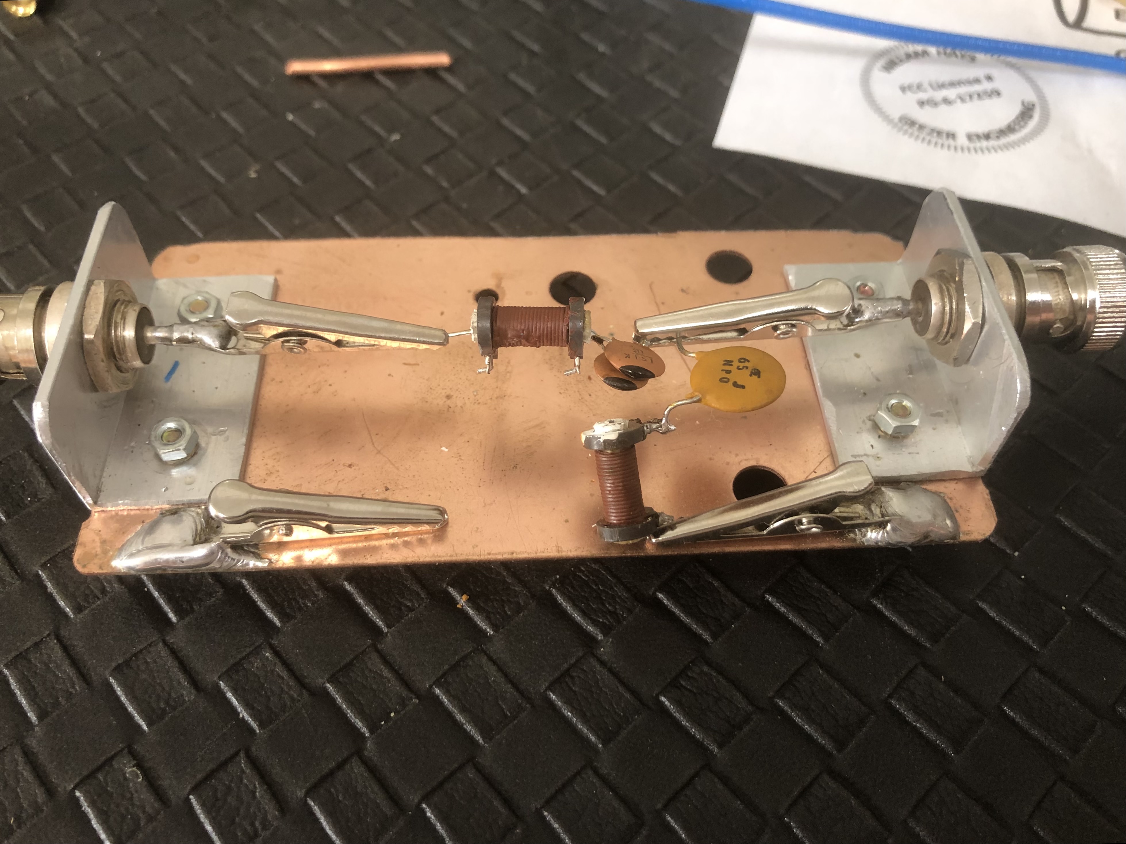
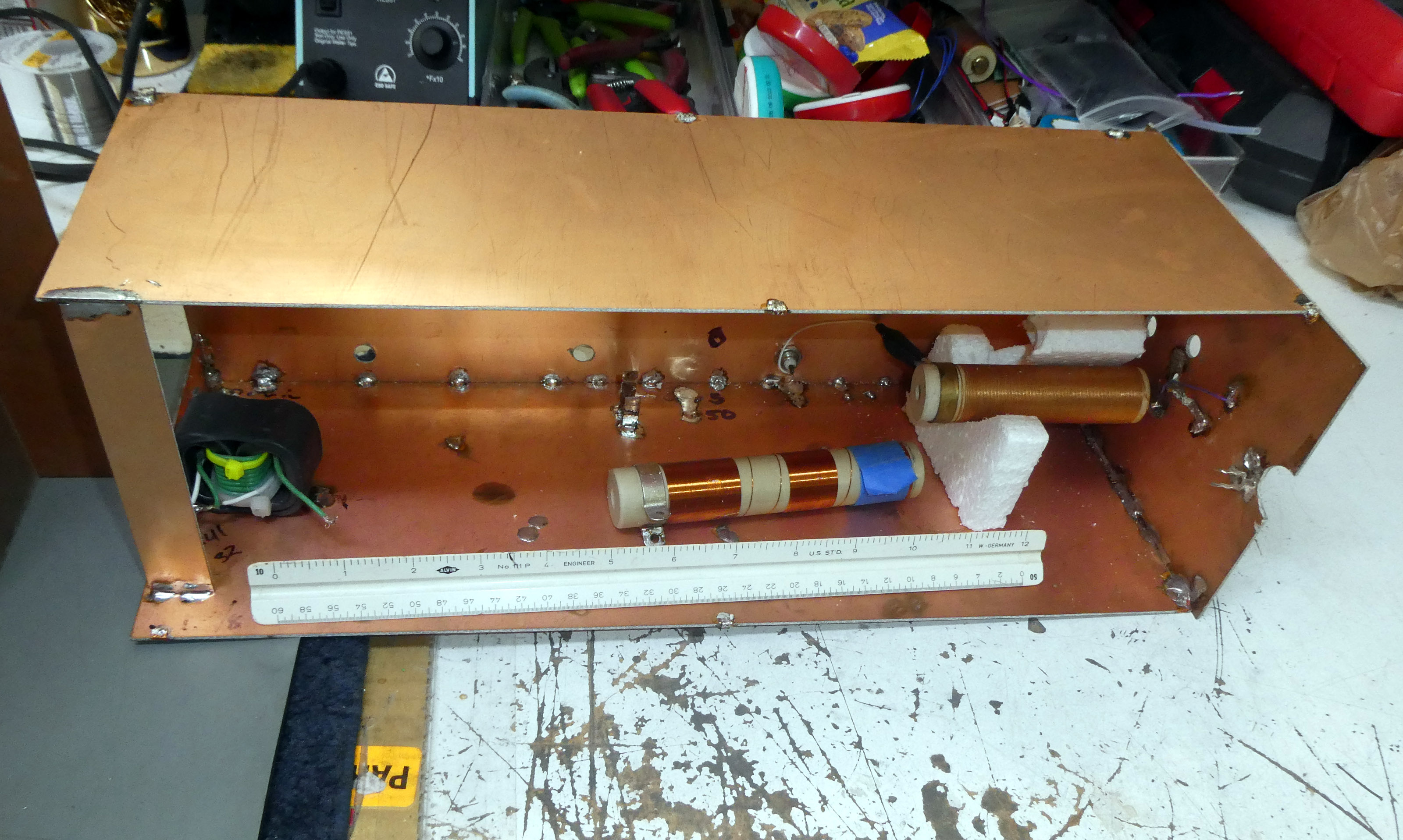
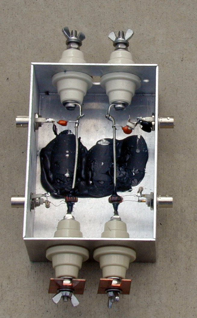
> Attached is my line balanced test fixture. I use it with a dual channel
vector voltmeter or a four port vector network analyzer. It has two current
samples and two voltage samples and requires external detection. This allows
a single point measurement of balance.
>
> 73 Tom
>
>
>>>
>>> On 9/24/2023 1:05 PM, W0LEV wrote:
>
>>>
>>>> Since I use open wire for my transmission line to/from the antenna
feedpoint, I built a little box for the purpose of reading current on each of
the two conductors. Each of the two conductors is outfitted with a current
probe similar to that illustrated in the reference. I can switch between the
two current probes. I have tested and calibrated each using a non-inductive
resistor across the "output" to read equal values. In place on the feedline,
if both current probes read the same, I know my common mode choke is doing the
job.
>>>>
>>>>
>
>>>>
>>>> Dave \- WØLEV
>
>>>>
>>>>
>
>>>>
>>>> On Fri, Sep 22, 2023 at 6:28 PM The Greene Family
<[cvgreene@snet.net](mailto:cvgreene@snet.net)> wrote:
>
>>>>
>>>>> As W8JI said, these small VNAs are really great for a lot of
applications, but they are limited once you get way outside the 50 Ohm
impedance region. Lots of articles have been written about that. Even the
very expensive VNAs are limited, but to a lesser degree. I guess you do get
something for 20 dB or so more money.
>
> And, as Tom has suggested, the actual performance of common mode chokes
depends largely on the environment they are used in.
>
> So, sticking with W8JI, have you considered using something like this to
measure common mode currents on your feedline?
>
> [Current Meter](https://www.w8ji.com/building_a_current_meter.htm)
>
> Test your chokes in actual use.
>
> 73,
>
> Clarke K1JX
>
>
>>>>
>>>>
>
> \--
>
>>>>
>>>> **Dave - WØLEV
> **
>>>>
>>>>
>
>>>>
>>>>
>
>>>
>>>
> [](http://www.avg.com/email-
signature?utm_medium=email&utm_source=link&utm_campaign=sig-
email&utm_content=emailclient) | Virus-
free.[www.avg.com](http://www.avg.com/email-
signature?utm_medium=email&utm_source=link&utm_campaign=sig-
email&utm_content=emailclient)
>>> ---|---
>>
>>
>
> \--
>
>>
>> **Dave - WØLEV
> **
>>
>>
>
>>
>>
>
_._,_._,_
* * *
