Scott KF7GGN 2025/08/11 17:08
Hi Sohail,
I'm not sure that the way you are using the NanoVNA to make the common mode
measurements is correct. The way I have been shown to do and have done
myself such measurements is to apply the same signal on both of the bifilar
conductors. You seem to have a single wire with the beads on it. I hope
this is not what you are building as a common mode choke because it will
not work. To get proper common mode current suppression, you need a
transmission line choke, which uses the bifilar winding comprising two
wires in parallel, or can be in the form of a thin coaxial cable. The
bifilar winding is wound around the toroid, or you can try stringing the
beads on a short length of coax.. The way to measure the common mode
current suppression is to solder one end of the bifilar wires (or center
conductor and shield of a coax) each to a 50 ohm resistor. The free leads
of the 50 ohm resistors are shorted together and connected to the S11
terminal of the NanoVNA. At the other end, the two wires (or inner
conductor and shield of a coax) are again soldered each to a 50 ohm
resistor, which the free leads are shorted together and connected to the
S21 terminal. Then set up the NanoVNA to for through mode, your frequency
range, and to display the data on the LogMag display to see how much
suppression you are achieving. Ideally you should have at least 20 dB
suppression of the signal, which would be the least amount of attenuation.
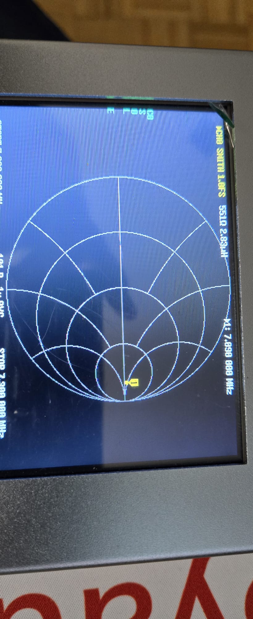
Hopefully, the attenuation increases as you sweep to higher frequencies. In
your photos, you are showing the Smith chart display, which is only for
impedance or reflection measurements as you may know. The Smith chart does
not show the signal suppression. However, you can and should also measure
the SWR of the choke as well. This can be done by looking only at the
reflections from the S11 terminal with the NanoVNA . Those may be displayed
on a Smith chart. I will check on the exact procedure, but basically, you
want to make sure the SWR of the choke does not exceed 1.5 or maybe 2 at
most. If so, then either the impedance of the bifilar winding is not close
to 50 ohms and causing reflections, or it could be that the ferrite mix is
probably not the best, and you may want to switch to mix 43. But this may
depend on the frequency range of interest.
For more authoritative information, see TRX Lab YouTube videos #100 and
#101 on common mode choke baluns and the making/measuring thereof. This is
a very good series from Germany. He uses a benchtop VNA to do the
measurements, but it makes no difference if you use a NanoVNA. He shows the
proper way to make the connections and what to look for in the data.
Please let us know if this helps.
73,
Scott KF7GGN
On Sun, Aug 10, 2025 at 10:00 AM Sohail Anjum via groups.io <anjum_sohail=
hotmail.com@groups.io> wrote:
> Hi Team,
>
> I need a confirmation from group member what I am doing is correct.
>
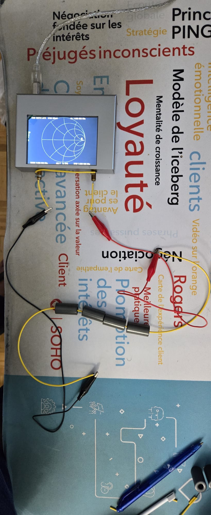
> I am in the process of making RF chose for my HF antenna. Instead of
> making an ugly balun, I decided to make one from the Mix 31 ferrite beads.
> I made one last time for my vertical antenna but at that time I board
> MFJ-259B from friend of mine to measure it. This time I have my own nano
> vna. I think they way I have setup the nano vna to measure the choke is
> correct but need a verification. I have placed 4 beads and the impedance is
> around 550 ohm plus. I am posting some pictures and a video. Its not a best
> setup but just want to see if the impedance is 50 x 10 or more. I can add
> more but main thing that I would like to know is this showing correct that
> choke is 550 plus ohm.
>
> Thank you,
> Sohail VE3ITU.
>
>
>
--
Scott Gilbert
KF7GGN
[image: BCARES]
