Beware of cheap underperforming clones

As of 2022 there are many badly performing clones on the market. V2/3GHz NanoVNA uses parts like ADF4350 and AD8342 which are costly and clones have been cutting costs by using salvaged or reject parts.

See official store and look for V2 Plus4/V2 Plus4 Pro versions only to avoid getting a bad clone. We have stopped selling V2.2 versions since October 2020, so all V2 hardware that are not Plus or Plus4 are not made by us and we can not guarantee performance.

NanoVNA V2 Forum

Note: this page is a mirror of https://groups.io/g/NanoVNAV2.
Click here to join and see most recent posts.

Looking for an analysis


barnc4br 2021/01/07 08:27

I am trying to analyze a TV antenna with little knowledge.
If someone can give me their take on these screenshots, I would greatly appreciate it.
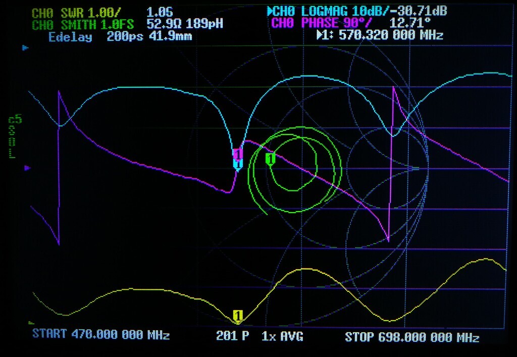
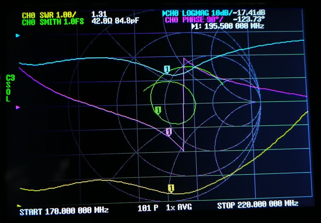
It is a VHF/UHF combo that I built.
The Nano was calibrated at 50Ω. I understand that doesn't Yield accurate results.
The antenna is connected via a 300Ω to 75Ω balun, a 2' coax, and SMA to F adapter.
I did add a delay for the adapter.
I understand the effects the cable and balun may have, and that not calibrating at 75Ω has affects but what I would like to know is if these screenshots tell me anything about the response of the antenna. I have more, if needed, with different markers positions.
thanks

Jim Allyn - N7JA 2021/01/09 18:11

Well, your NanoVNA screenshots tell us the antenna is fairly well matched. The purple phase trace doesn't really tell us much of interest. The other 3 traces all tell the same story, presented in 3 different ways. The SWR is reasonably low across the band. The blue trace shows return loss: you run a signal into something (like your antenna), and some of it gets bounced back. Ideally, you would want all that applied signal to be radiated by the antenna, so you want return loss to be a large number. The return loss is 10 dB or better (SWR = 2:1) over much of the band, and as good as 30 dB (SWR = 1.065) at some frequencies. Yeah, I know those of us who are hams or CBers try to keep our SWR as low as possible, but 2:1 over a broad frequency range is pretty good. It's easy to get good SWR at one frequency, getting good SWR over a broad frequency range is tougher, and your antenna looks pretty good for as broadband as it is. What isn't shown here is how much gain (if any) the antenna has. How well does it hear? If it hears good, I'd say you've done a fine job with your antenna. Everything in antennas - and a lot of other electronics - is a series of compromises. People like to joke that an omnidirectional antenna is one that works equally poorly in all directions, and a broadband antenna is one that works equally poorly on all frequencies.

If I were checking an antenna with a NanoVNA, I would probably use either the return loss trace or the SWR trace (most likely the return loss trace), and probably turn the others off. Most people with a lab background will probably choose to display return loss, while those with a field background will probably choose to display SWR. The phase trace (purple) doesn't tell us much of interest. The green trace (Smith chart) would be useful if you were trying to improve the match, as it will tell you if the impedance is inductive, capacitive, or purely resistive.

Do let us know how well it hears!

barnc4br 2021/01/11 09:04

Thank you Jim. So it looks like the UHF portion is pretty good. The VHF portion could probably be improved at the high end by shortening the elements slightly to reduce the SWR at the high end, would you say?
This is a Gray Hoverman design that I did not put the reflectors on so it is bi-directional and appears to receive better than I expected it to. I have stations to the ESE and WNW so the bi-directional aspect is perfect for that. One to the WNW is about 55 miles away.

D Nordquest 2021/01/11 10:39

Interesting message.

Is the antenna design posted somewhere?

barnc4br 2021/01/12 13:11

There is lots of stuff posted - some of it has gone away but let me list what I have

This is a search I did on digitalhome - many links
https://www.digitalhome.ca/search/32685/?q=%22gray-hoverman%22&t=post&o=relevance

https://www.youtube.com/watch?v=CfTO69K2arY
https://www.youtube.com/watch?v=hrRiBomPih8

This is the most elaborate but it doesn't include the VHF top hat elements
http://www.jedsoft.org/fun/antennas/dtv/gh.html

This guy is a piece of work, but he is a true tickerer. He added a different top hat than I have, but it works.
https://www.youtube.com/watch?v=Yavd9-rl5qQ

There are even 4nec2 files floating around. I wouldn't say my build is perfect and without the reflector the dimensions are probably wrong but it does work pretty well.

Jim Allyn - N7JA 2021/01/13 01:53

On Mon, Jan 11, 2021 at 09:04 AM, <barnc4br@gmail.com> wrote:

> The VHF portion could probably be improved at the high end by shortening the
> elements slightly to reduce the SWR at the high end, would you say?

Tough to say, actually, for several reasons. You are working with a system impedance intended to be 75 ohms, but the VNA is calibrated to 50 ohms. That is part of the reason the SWR looks high at the high frequency end. It's probably not as bad as it looks. You could recalibrate your VNA to 75 ohms and see what it looks like that way. Also, to see what the SWR is *at the antenna*, you need to remove the effects of the 2 feet of coax you have from your measurements. Is it 50 ohm coax, or 75 ohm coax? Knowing that and the velocity factor of the coax (how fast signals move in that particular type of coax - it will be slower than the "speed of light") you could plot what the real impedances are at the antenna on a Smith Chart. The impedance looks to be inductive (top half of the Smith Chart), but impedances are rotated around the chart by the coax, so it could actually be capacitive. It's not hard to use a Smith Chart, but there is a bit of a learning curve. Also, are there any stations in your area at the top of the VHF band? If not, then you really don't have any reason to care what the SWR is there. Additionally, when the input impedance of a receiver is rated at 75 ohms, that means "nominally" 75 ohms. It could be anywhere from maybe 15 or 20 ohms to perhaps 200 ohms or greater. And, to further complicate things, if you're dealing with weak signals, best impedance match isn't necessarily what you want, you want best noise figure. You're probably already approaching the point of diminishing returns. Rather than trying to tweak the last tenth of a dB out of your current antenna, put up a bigger antenna, and put it up higher. Or build an array of 2 or 4 or 8 of the antennas you have now. Or add the reflectors that you left off of your antenna. That would almost certainly gain you more in signal strength than tweaking the SWR will. Ah yes, but then the antenna would be more directional, and you'd need to be able to rotate it. Everything in electronics, and perhaps especially anything radio related, is a series of compromises.

To reply to this topic, join https://groups.io/g/NanoVNAV2