Joe Smith 2021/08/12 10:40
After the constant direct emails from you, which help no one but yourself, I had added you to the SPAM filter. I certainly understand your not wanting to make your posts public but at the same time, I only have so much time and it makes little sense spending it on individuals in private discussions. While I'm sure you see yourself as my customer, let me be clear, you're not. The software was not written for you, but everyone is certainly free to use it. Personally, I recommend people not waste time with it and stay with the open source software that is available.
1. Calibration Error - Always on even if sweep range is within calibration range - OK to ignore ?
With the sweep range inside the calibration range, there should be no error. Without my crystal ball, I have no idea what you are doing or seeing. If there is a problem with the software or something in your procedure and you would like to try and work through it, the easiest thing to do would be to make a video, or document each step. Start with powering on the VNA. It's up to you to provide enough detail so others can attempt to replicate what you are seeing.
"... however it is necessary to "normalize" level ..."
While I have covered it a few times, it's worth pointing out that in many of my videos and posts, I won't take the time to calibrate the VNA. In some cases I may seem flippant with my attitude towards the subject. There are a few reasons for this. Many VNAs can output good enough data without calibration to get me close enough. In many cases, I am able to get by with using normalization. There is also wear and tear on the standards. In my case, I do not own a set of metrology grade standards and would have little use for them for my home projects. Still, even my home made standards have a limited life. It also takes time to perform a proper calibration which brings up my last point. I am lazy.
If I do need to measure my VSWR down to thee places past the decimal (had a radio hobbyist tell me that), I will normally make all of my measurements with the VNA uncalibrated. If everything makes sense and I can see the numbers coming out to what I expect them to be, then I take the time to calibrate and make my final measurement.
My first VNA (HP8754A) has no way of performing a SOLT and only has normalizaion (with an HP8501A). That's actually the reason that I first wrote the software was to allow me to calibrate that unit. It's up to the user to understand what they require to make their measurement. Not just the standards, how to use them but also the VNA, cables, torque wrenches, adapters. The best thing about these low cost VNAs is your out little cash if you screw something up. They are a very good starting point for those wanting to learn some of the basics.
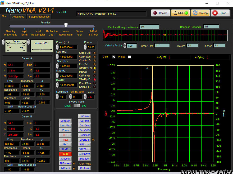
2. Resistance value is negative sometimes - OK to ignore ?
I assume the user can answer that.
3. How to move cursor B to min or max using pushbuttons ?
It should have been obvious that both cursors are effected when selecting the buttons you mention. FYI, I may change how these work in the future. For example, Max I've thought about moving A to the highest and B to the second highest. Maybe adding a Max/Min button where A goes to max and B to minimum. For now, I don't have a use for any of it but will say the software has certainly evolved since I first wrote it for my HP8754A.
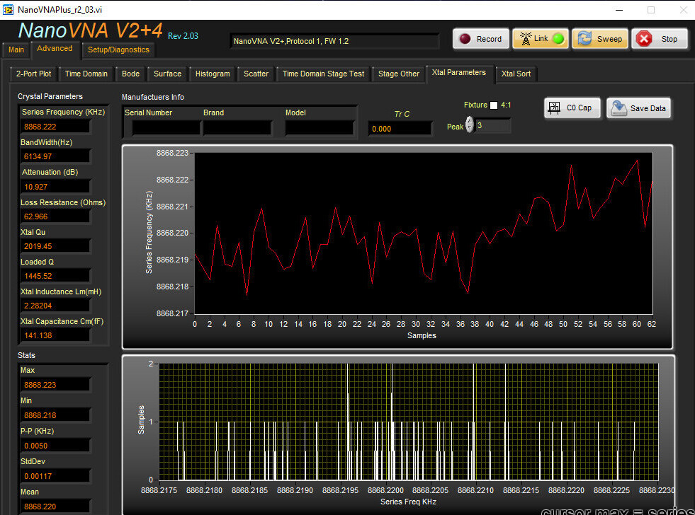
4. P - P (hz) on crystal parameter - what is P-P ? "...I cannot find any explanation in the manual or You Tube tutorials."
First, the manual is certainly not all inclusive. It covers some basics on how to use the software. This is one difference between a home project and what one may expect from a purchased commercial product.
In the case of your specific question, once again I thought this was rather obvious and because these numbers are not used as part of the typical calculations, I chose to not spend any time going over them. All of the statistics are for the histogram to the right. Look at your screen shot and look at the histogram. Max is towards the right, Min to the left. P-P(KHz) is Max - Min. Standard deviation is taking into account all of the data collected. Visually, we can see it has a gaussian distribution and the Mean works out close to the center.
5. page 30 - missing m
I suspect there are many small errors like this but most readers are able to understand what is being described. I'm actually surprised that you wouldn't have mentioned the use of "K" vs "k" in the software on the page you posted. That's something I really should take the time to correct. I am really bad when it comes to case and units but the context normally saves me.
6. page 94 - beach towel phrase does not make sense
I thought it was obvious and another member did a fine job covering it.
7. Will 2 SPDT PIN diode switches (plus SPST relay for status of relay) work for a transfer relay ?
Could you share your USB control details ?
That's really up to the designer to come up with what ever circuit meets their criteria. The manual covers the use of a transfer relay. What specifically were you not understanding?
