Roger Henderson 2021/10/04 19:07
The last couple of messages in the below thread are also worth a read.
There is an article from the HP VNA guru Joel Dunsmore, and a newer article
from Brian (virtualparticles) who is an RF guru from Copper Mountain.
https://www.eevblog.com/forum/rf-microwave/can-a-siggensadirectional-coupler-be-used-as-a-poor-mans-scalar-analyzer/msg3631413/#msg3631413
On Mon, 4 Oct 2021 at 18:36, OK1VAW <ok1vaw@volny.cz> wrote:
> Hello,
>
> It is not a pure Wheaston Bridge, but loaded resistive bridge. The main
> difference is, that the diagonal (where you put the Galvanometer with high
> impedance) is loaded with a 50 ohm too. In most cases of reflectometric
> bridges there is a balun to get the diagonal output asymetrical with one
> pin grounded. If you do the math (and do not forget to use the 50 ohm
> generator - voltage source in series with 50 ohm resistor), you should get
> the power getting from diagonal in proportion to reflection coefficient.
>
> Here is detailed description from the Rohde&Schwarz ZRB2 bridge manual.
>
> http://ok1ufc.nagano.cz/radiotechnika/RF_Bridge_schema/SWR_Bridge.pdf
> Dne 03.10.2021 v 18:31 spam@gamma-kappa.com napsal(a):
>
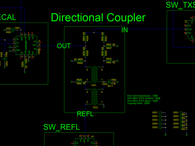
> I have some difficulties on understanding the design of the coupler in the
> NanoVNA v2. From what I understand is that this is a wheatstone bridge but
> I have some problems understanding the initial design process for that and
> where all the additional resistors are coming from. What was the initial
> design process to come up with 10dB transmission.
>
>
>
>
