John Gord 2020/09/10 23:25
It looks like the CW phase noise problem on my older NanoVNA-V2 is indeed the 24MHz crystal oscillator.
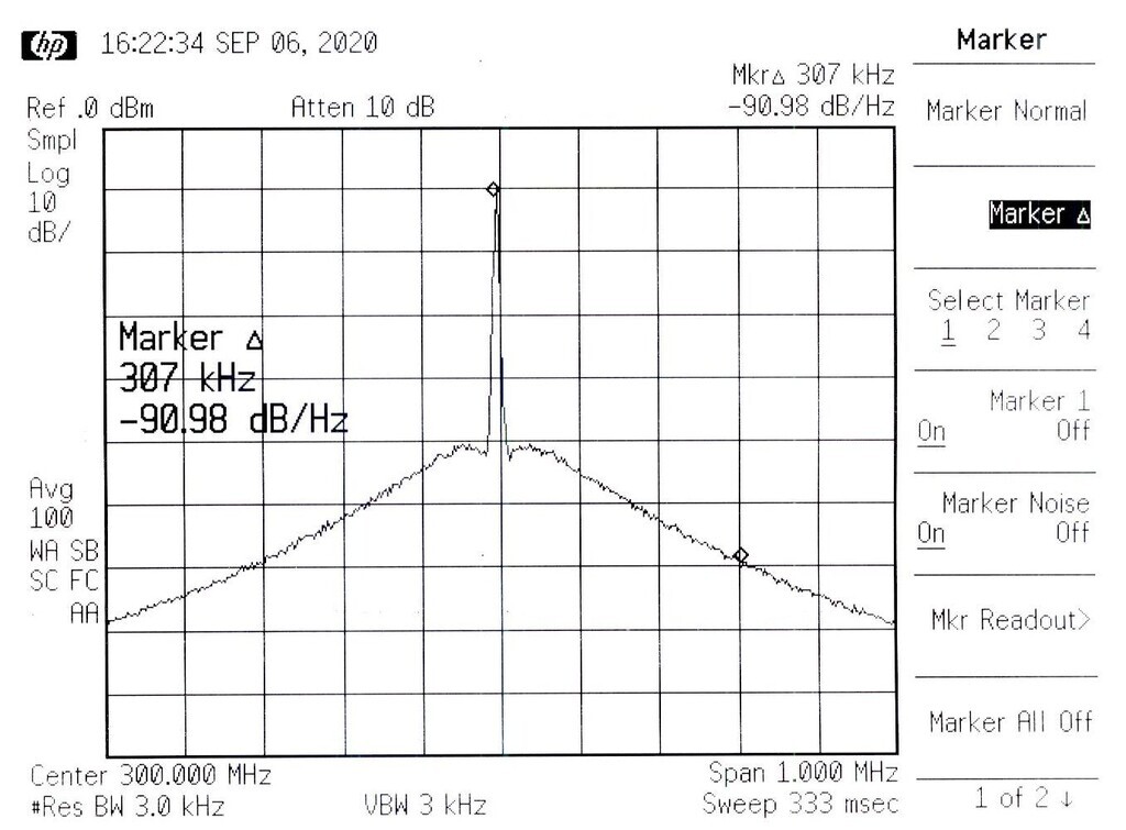
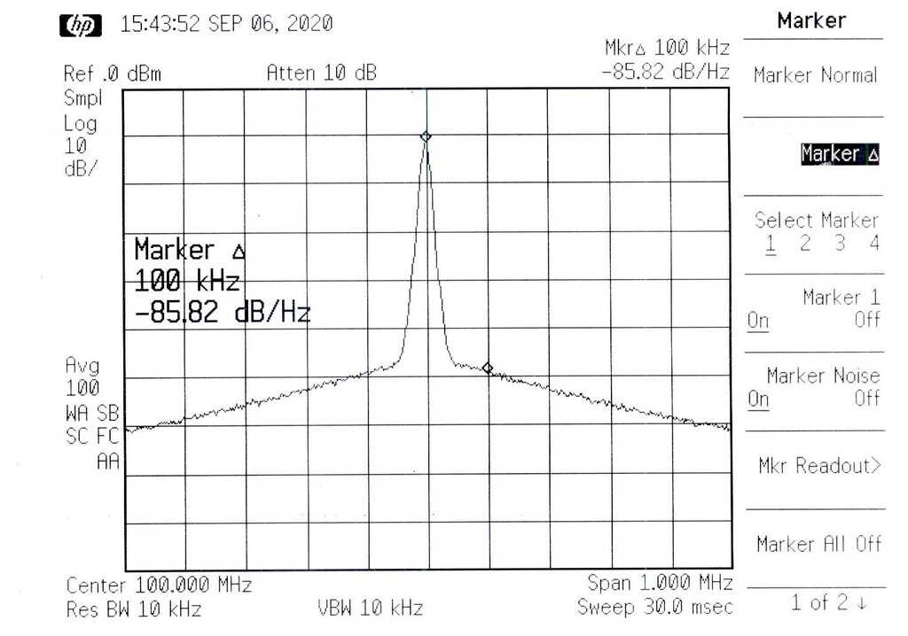
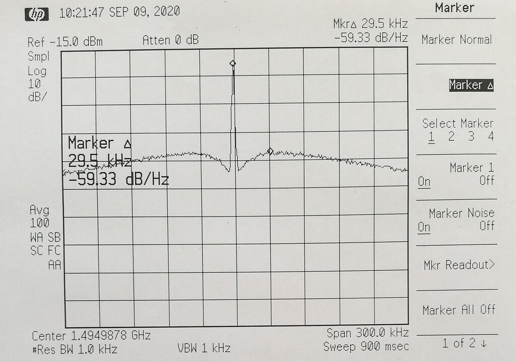
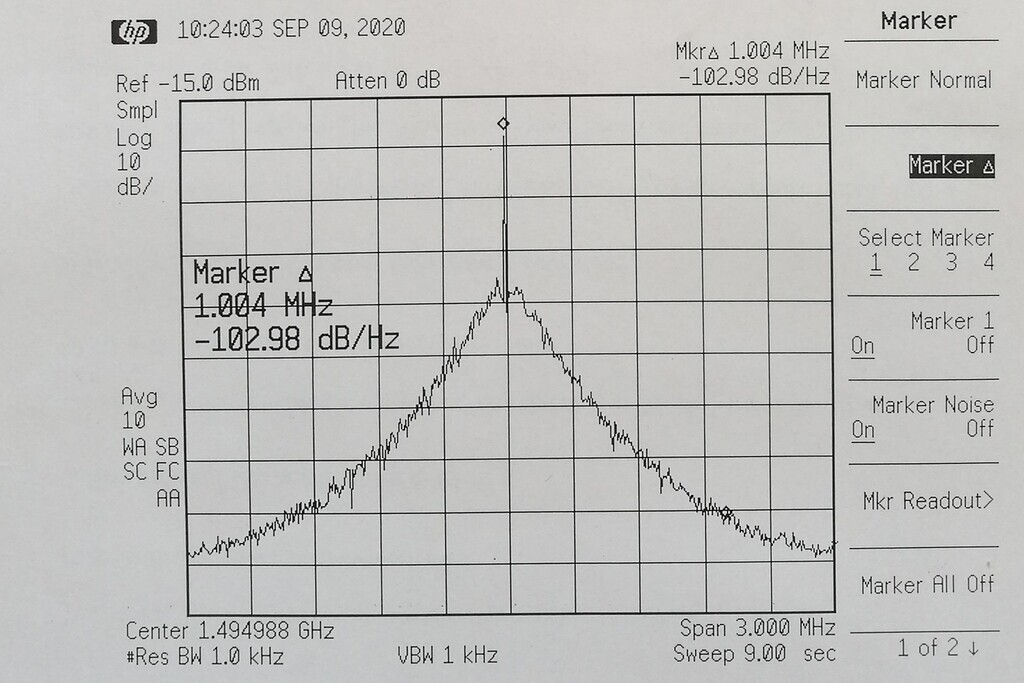
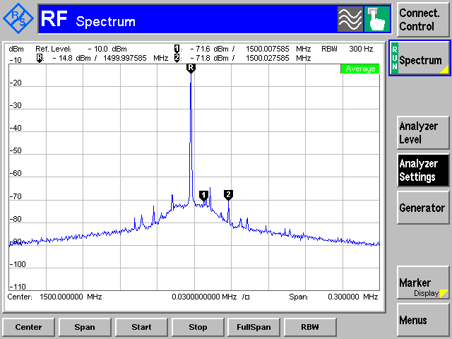
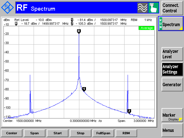
I checked the 24MHz oscillator outputs directly, and the noiser one (marked YXC 24.000 T1A) measured -100 dBc/Hz at 20kHz offset, while the better one (marked BN24.0 D745) measured -116dBc/Hz. I fed the older -V2 with 24MHz from a signal generator, and the 150MHz output improved from -82dBc to -102dBc.
As I said earlier, the normal VNA functions don't seem to care about the extra phase noise. I suppose I may replace the noisier crystal oscillator someday, but for now I will just use the more recent unit when I want a clean CW signal.
I should note that the earlier 24MHz oscillator fed a 3v p-p signal to the Si5351, well above the 1v p-p recommended. Reducing the signal level to 1v p-p did not help, but did keep the ac coupled Si5351 input from being driven below 0v. I had worried about that turning on some internal junctions and injecting substrate current, perhaps causing the phase noise. The later 24MHz oscillator runs at the recommended 1v p-p.
--John Gord
> On Tue, Sep 8, 2020 at 03:25 PM, John Gord wrote:
>
> >
> > Not all -V2s perform alike. (At least my two do not). The CW phase noise
> on
> > one of my units (purchased early in -V2 history) is
> > -86dBc, 130MHz, 20kHz offset, -82dBC, 150MHz, 20kHz offset.
> > A later unit has
> > -114dBc, 130MHz, 20kHz offset, -107dBC, 150MHz, 20kHz offset.
> > Both units are running the same firmware.
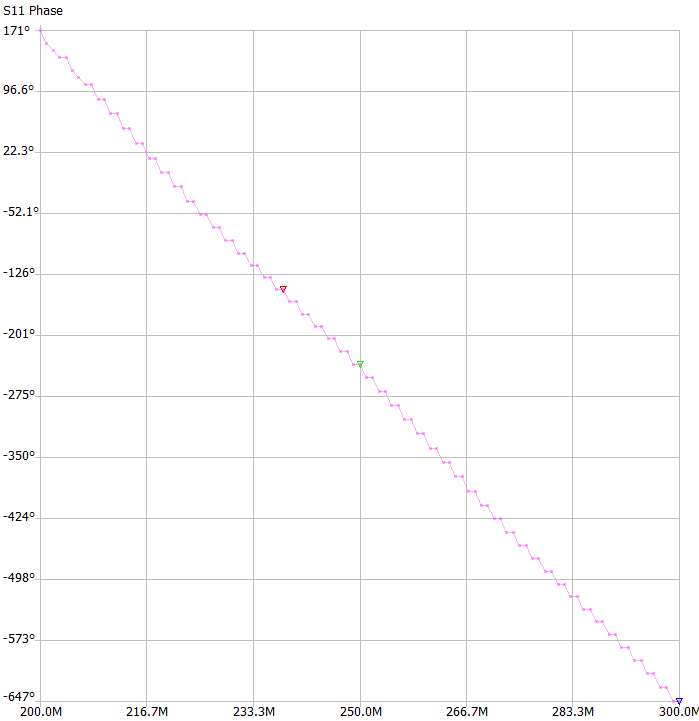
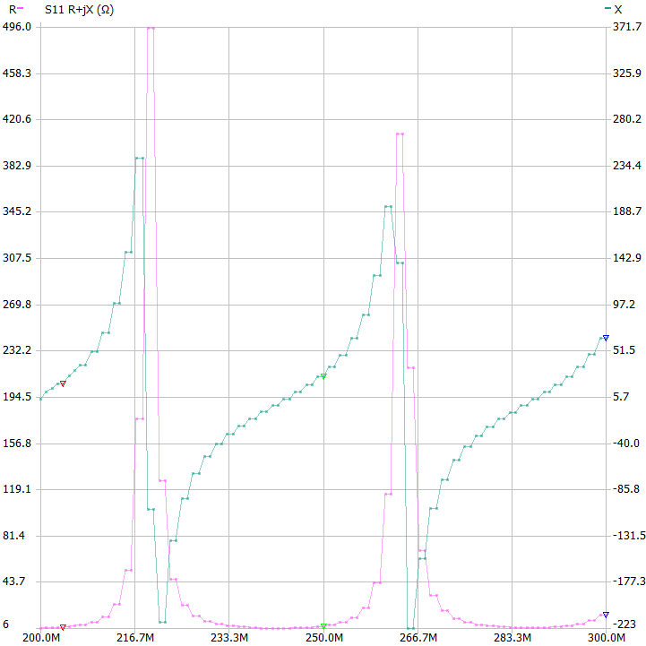
> > Both seem to meet specifications, in fact, I cannot see any big performance
> > differences in their "normal" VNA performance.
> > I suspect the problem is phase noise in the crystal oscillator of the poorer
> > unit, but I haven't taken it apart to verify that.
> >
> > --John Gord
> >
> > On Tue, Sep 8, 2020 at 02:24 PM, ok1vaw wrote:
> >
> > >
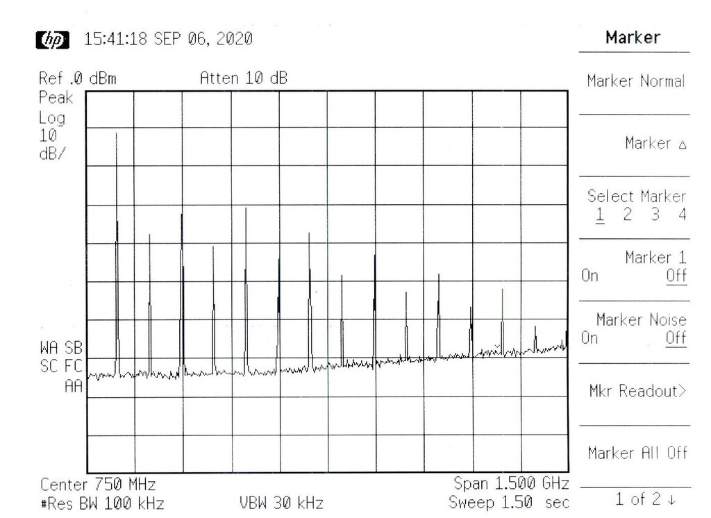
> > > i confirm no problem with measurement with switchabl firmware with
> > > measurement. Attached are some pictures with spectrum. It is clear, that
> up
> > to
> > > 150MHz the SI575 outputs the raw rectangle output rich with odd harmonics.
> > The
> > > output spectrum of the V2 itself corresponds to the sources inside.
> > >
> >
>
